Follow me on Facebook or Bluesky
Lets Begin
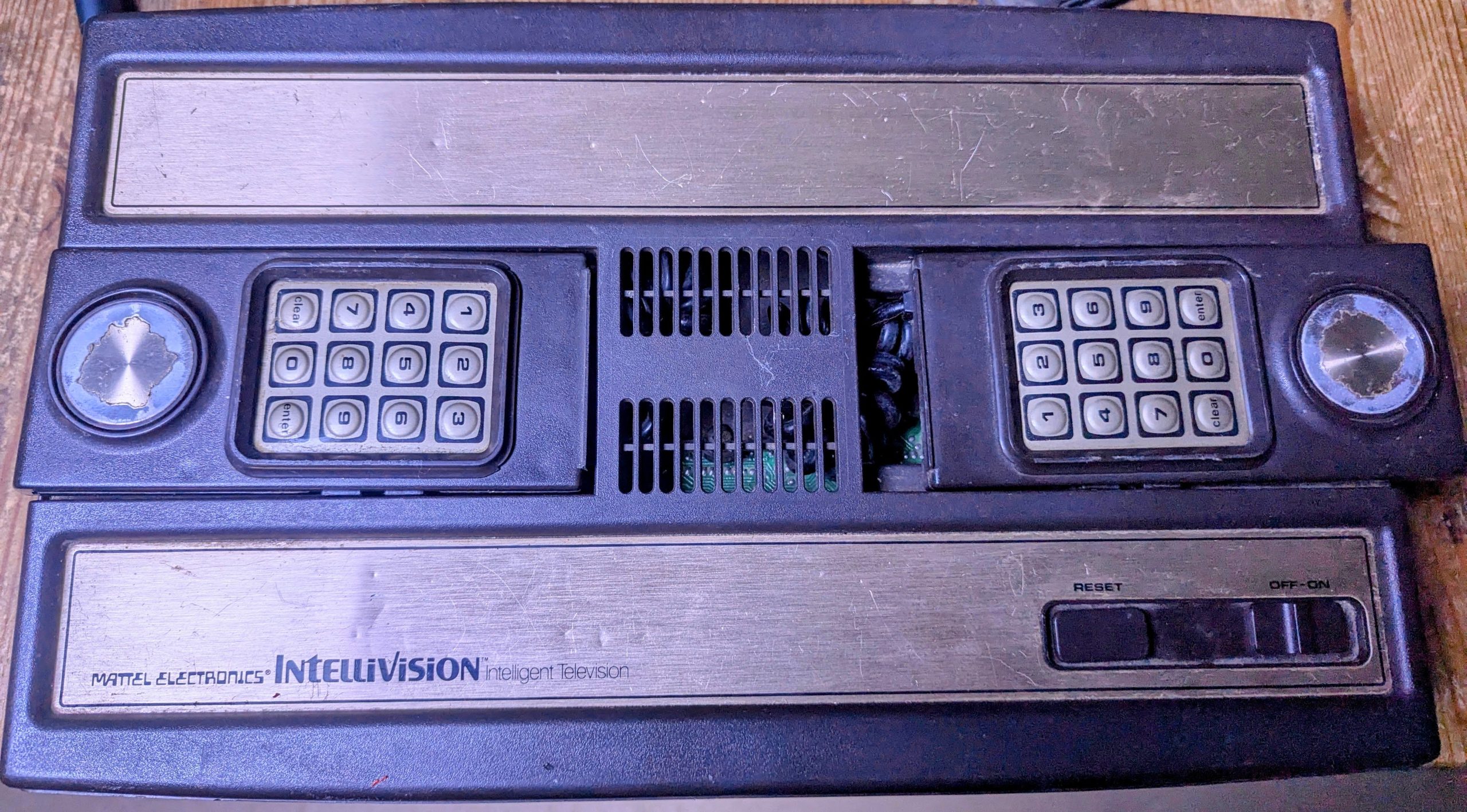
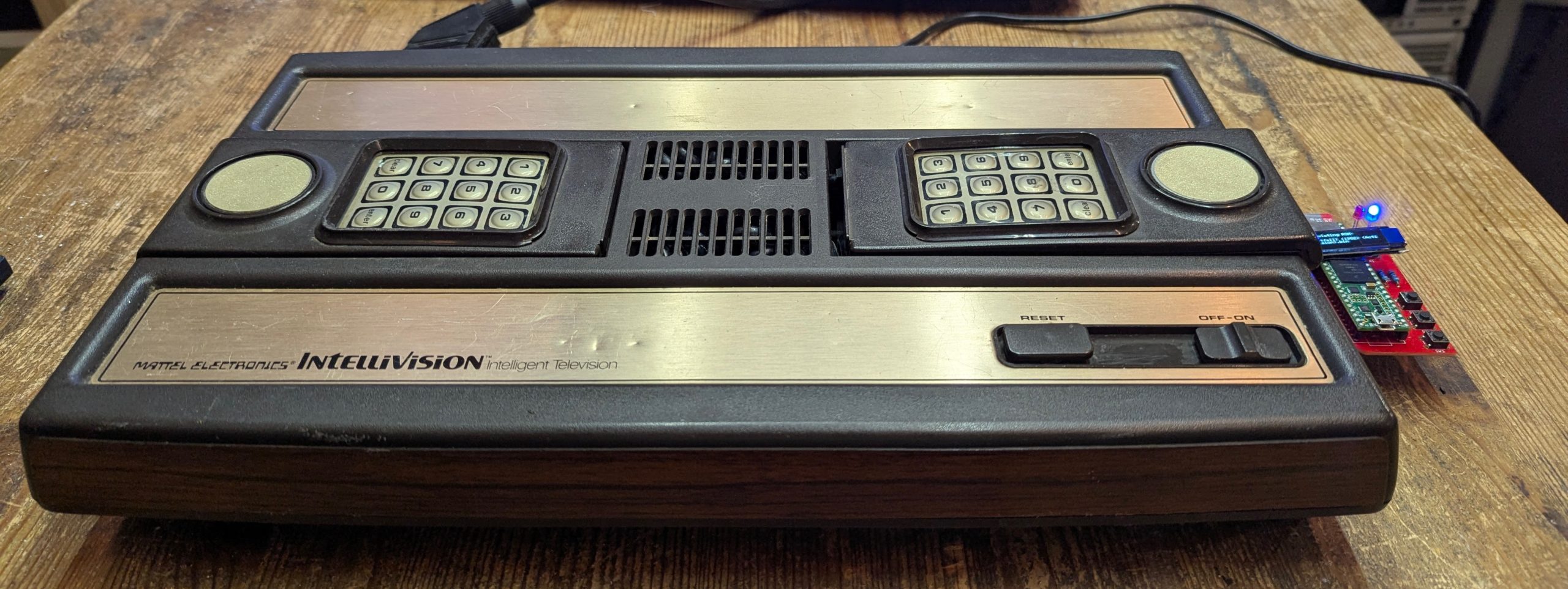
Intellivision Video and Controller Upgrades project is a warts and all journey of mistakes and learning. Please be advised that I am not an expert and do not recommend you try any of this unless you really know what your doing. The voltages inside the Intellivision can kill so beware.
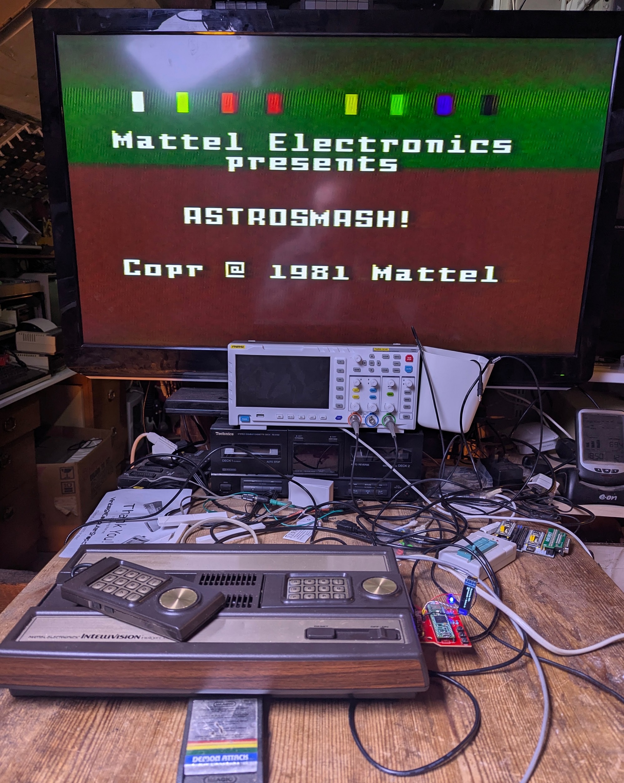
Stock Video Output
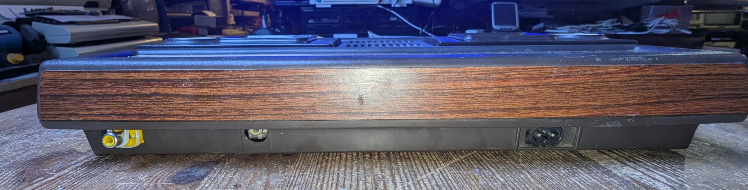
The only output of this console is RF video out. This is a combined video and audio output in one connector. A coaxial cable is plugged into the console and the other end plugged into the aerial socket of the TV. Back in the 80’s this was the norm for connecting consoles such as the Atari VCS or Grandstand and also for most of the 8bit computers of the time.
Composite Video
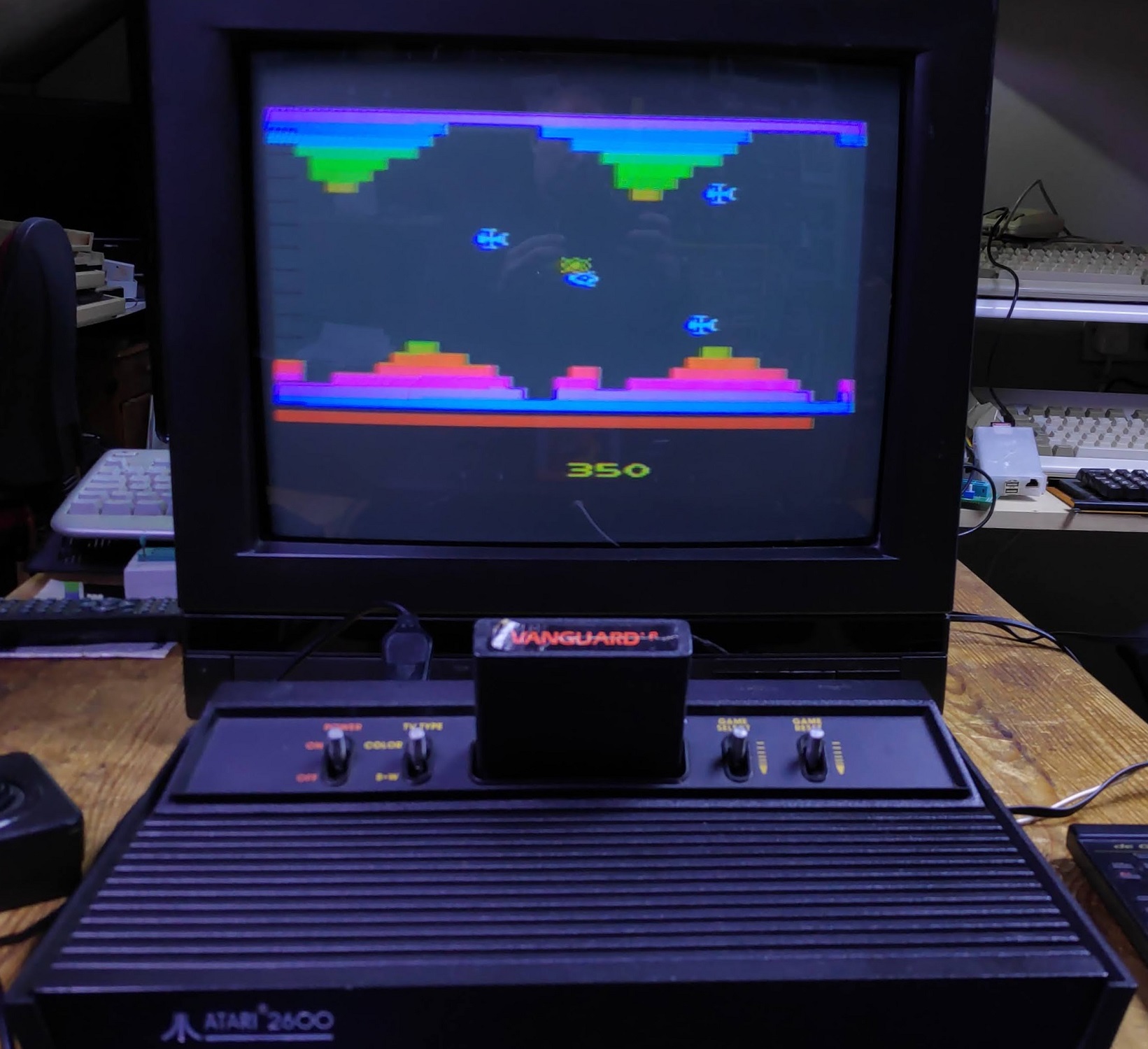
The stock video output using RF is very good compared with the Atari VCS
What decade are we in?
The problem is we are no longer in the 80’s and most modern TV’s do not respond well to these old RF signals. Fortunately most retro computers and consoles use some form of video output generator which is comprised of RGB (Red, Green, blue) and sync signals for each line and each frame of video. These signals are combined into composite video and then this is combined with the audio signal using a modulator to get our RF signal for our old TV.
Initially I tried this compositie mod on a bit of breadboard.

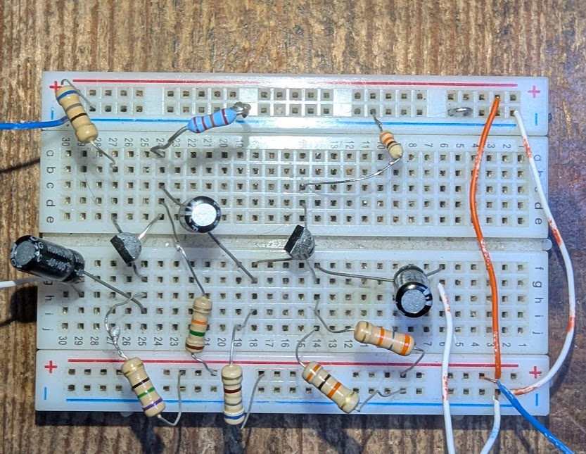
This composite output worked fine, as seen below, for about a minute
….and then this started to happen.
A disturbance in the top part of the display.
There is a daughter board for the video output with some potentiometers. So I thought I would have a fiddle.
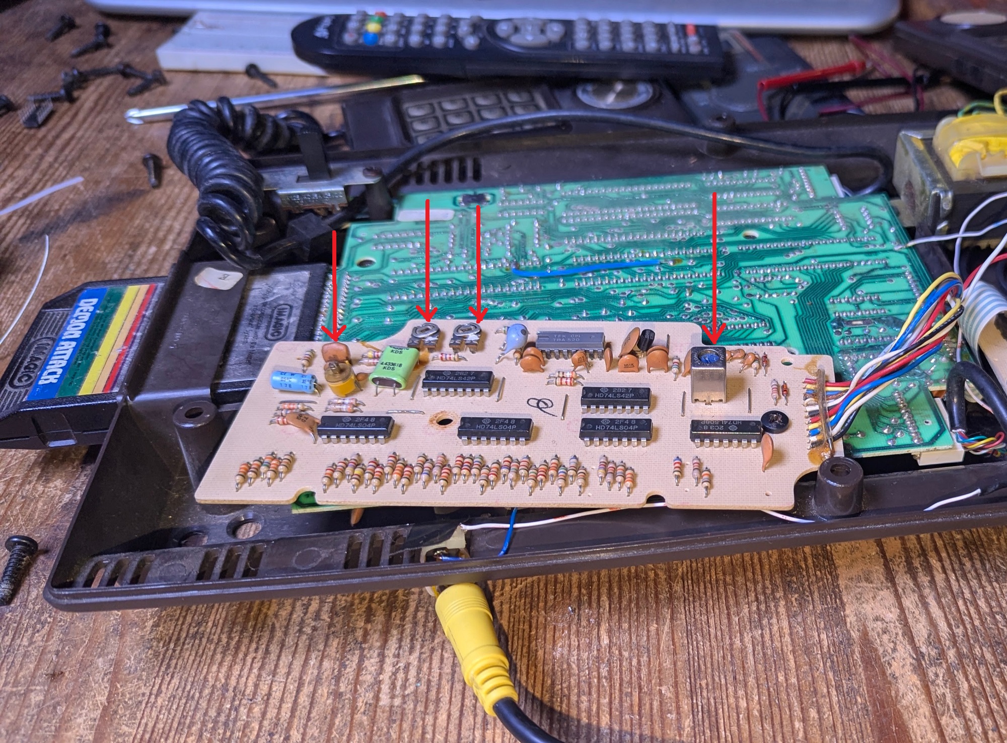
Sadly no amount of twiddling with the pots removed the distortion. They just make changes to the colour balance.
Its a shame because the composite video socket fitted quite neatly.
The disturbance therefore led me down a very dark path…
Hacking into the signals
The trick is to tap into the signals generated on the motherboard at the point the RGB is generated. The only problem is that sometimes these signals are very weak and need alot of amplification. And sometimes they don’t exist at all as is the case with the Intellivision. So is that the end of this project? Of course not!
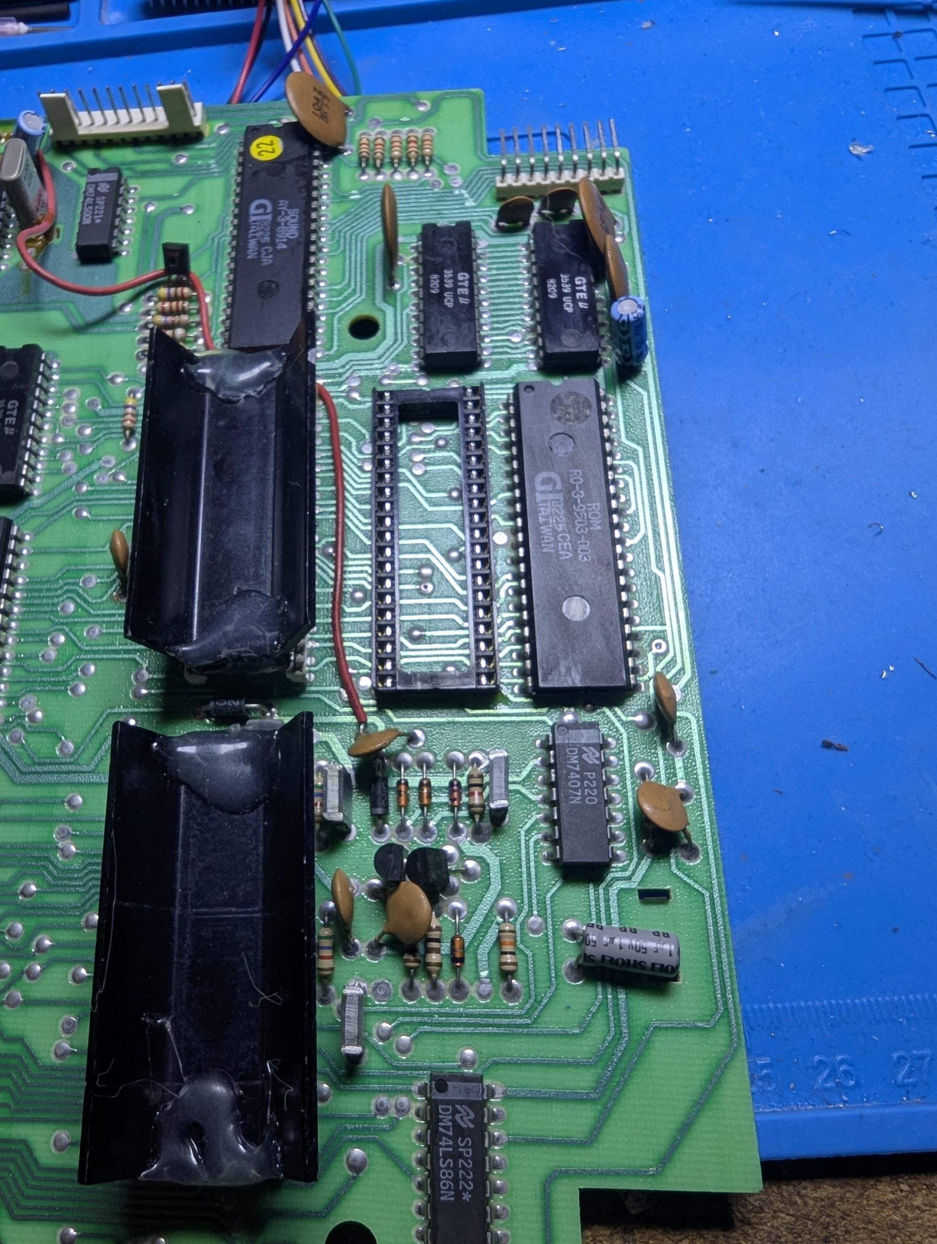
The intellivision video output is done by the Standard Television Intervace Chip or STIC. Five pins on this 40pin chip produce the video output.
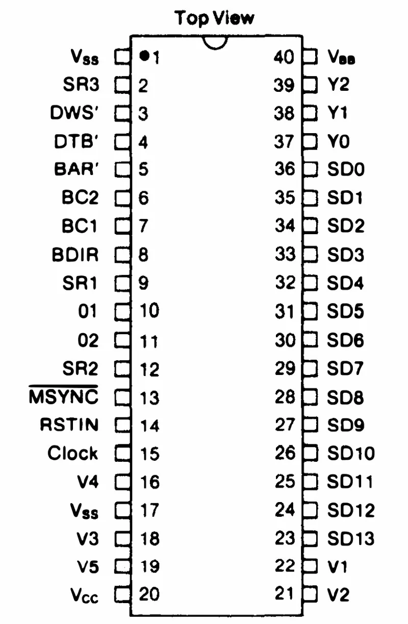
These are V1-V5 pins 16, 18, 19. 21, and 22. These determine the start of each frame and the color of each pixel. Pin 19(V5) is only high during blanking and the other four determine pixel color. This is quite an exotic method and will need some serious translation to generate RGB signals. The daughter board above effectively does this but outputs composite and not RGB.
Why Reinvent the wheel
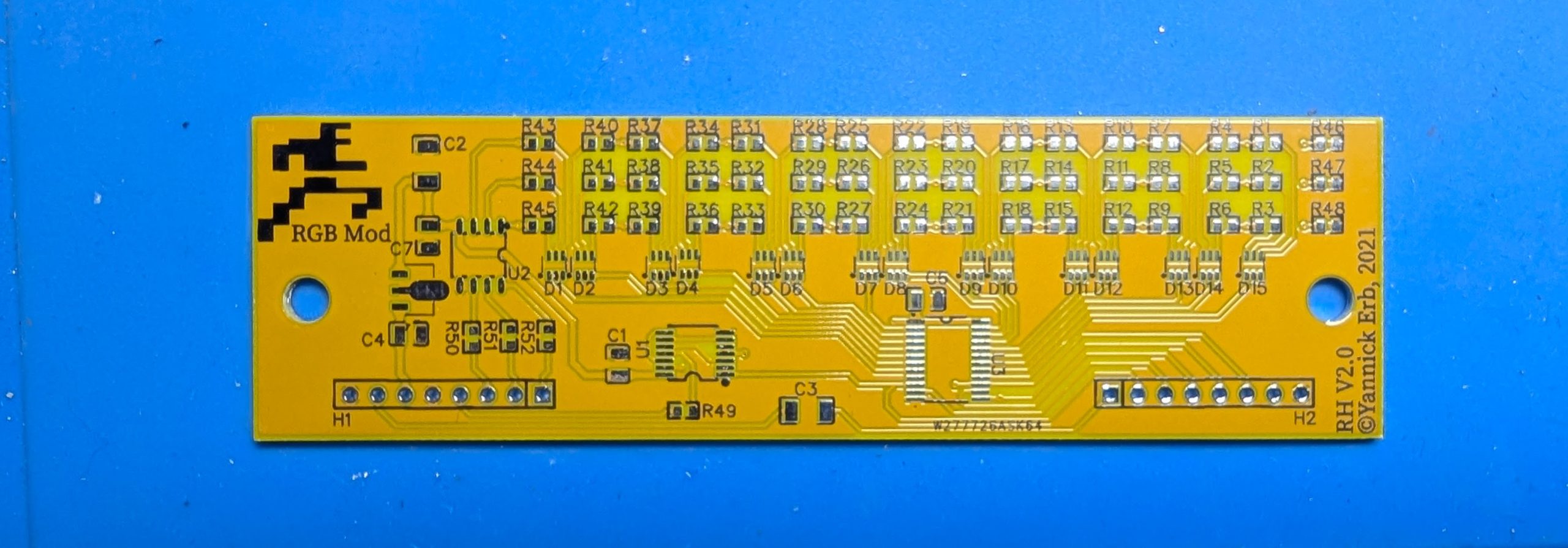
Fortunately some bright spark has already done this translation trickery (Yannick). He has developed a board which although quite complex does this job of translation quite neatly and he has made his work available to all for free. Thanks Yannick.
So after after a bit of reasearch on Atariage I felt armed with enough knowledge to attempt this. I ordered the circuit boards from my reliable supplier…

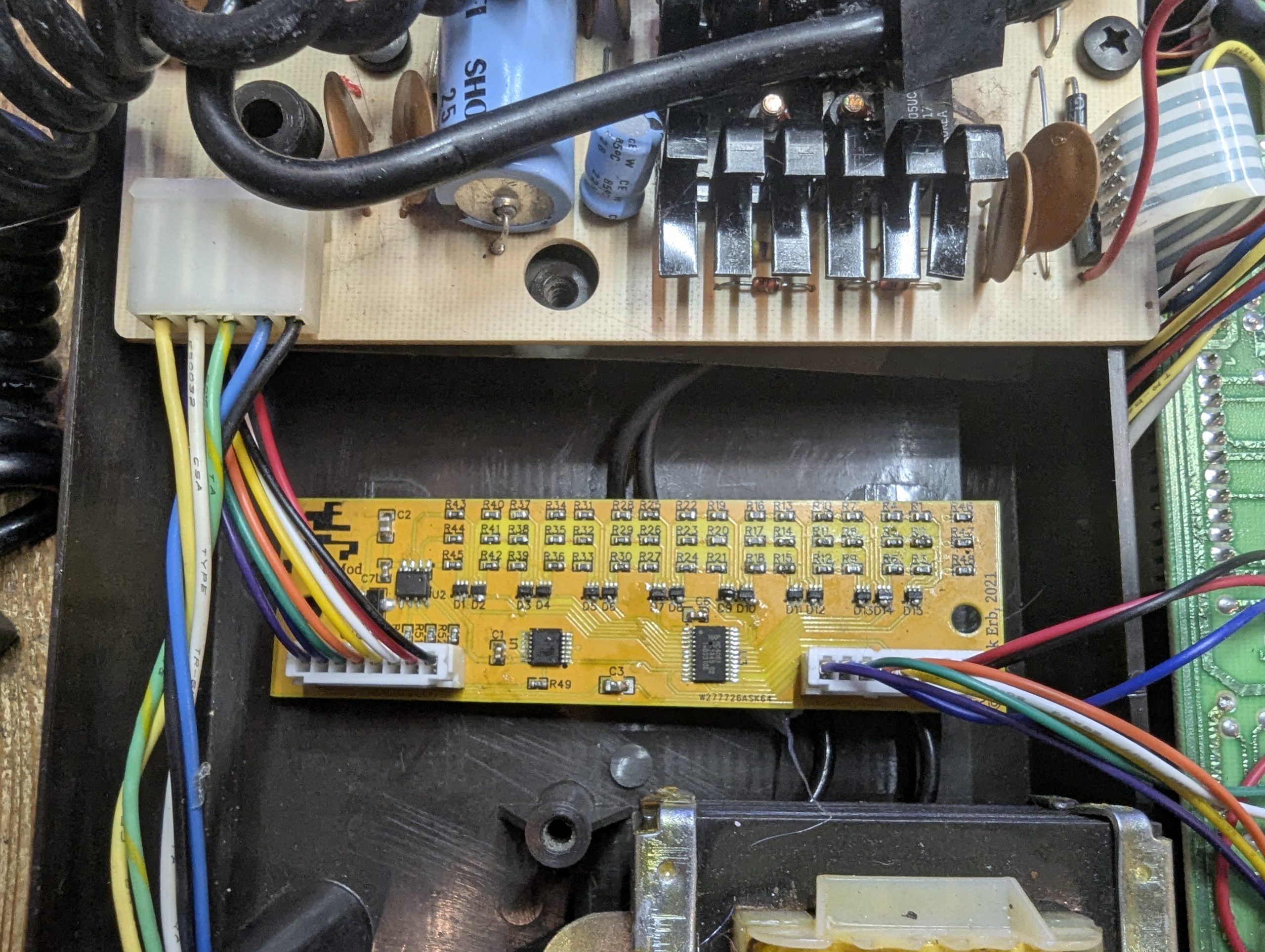
And they did not disappoint. After only a few days the boards arrive and look amazing in yellow.
Construction
I also decided to try low temperature solder paste so I could try this.
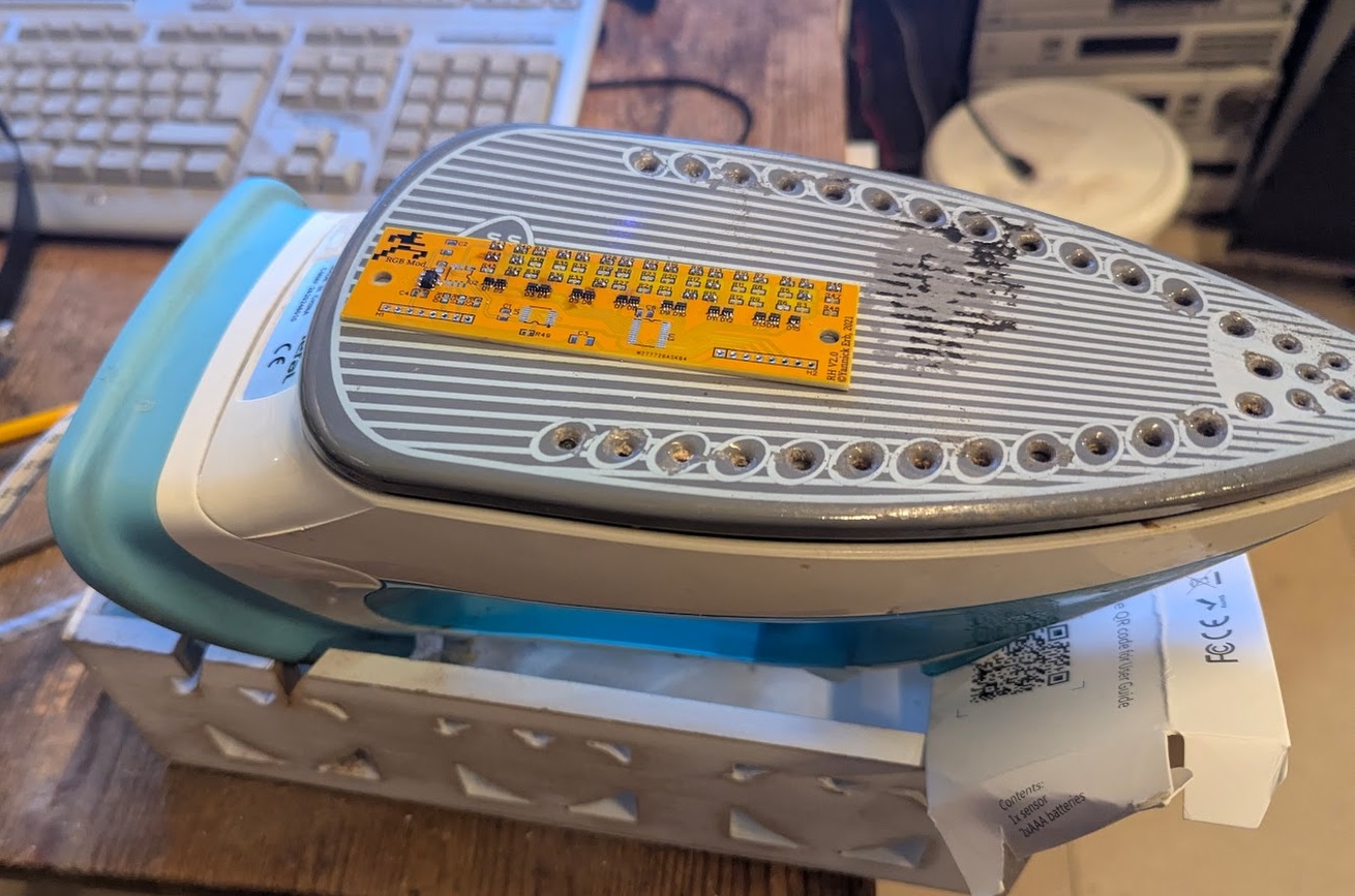
My DIY hot plate. Any old Iron?
I didn’t have all the components yet but my impatience got the better of me to try this “hotplate” method. I can always add the rest of the components later.
The components soldered almost perfectly but one or two components positioned themselves at odd angles so a brief touch of the soldering iron fixed them up.
The rest of the components arrived but there was an issue.
One of the components was not quite correct. It was the right device just the wrong size. In my haste decided to adapt it. Try and spot the slightly oversized component. I must apologise to Yannick for butchering his beautiful design and to PCBWay for this abomination but alas my patience knows no beginnings. It makes me wince every time I see this. Brace yourselves…
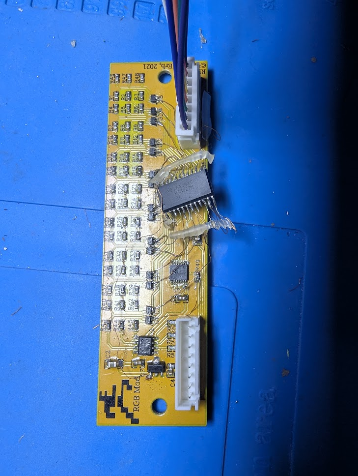
I will fix this when the correct components arrive but in the meantime I decided to continue with….. “The Frankenboard!!”
I did sanity check all the soldering which toned out perfectly.
Testing
Ok, time to install and test.
Now to flick the switch and carefully watch for smoke. Just kidding.
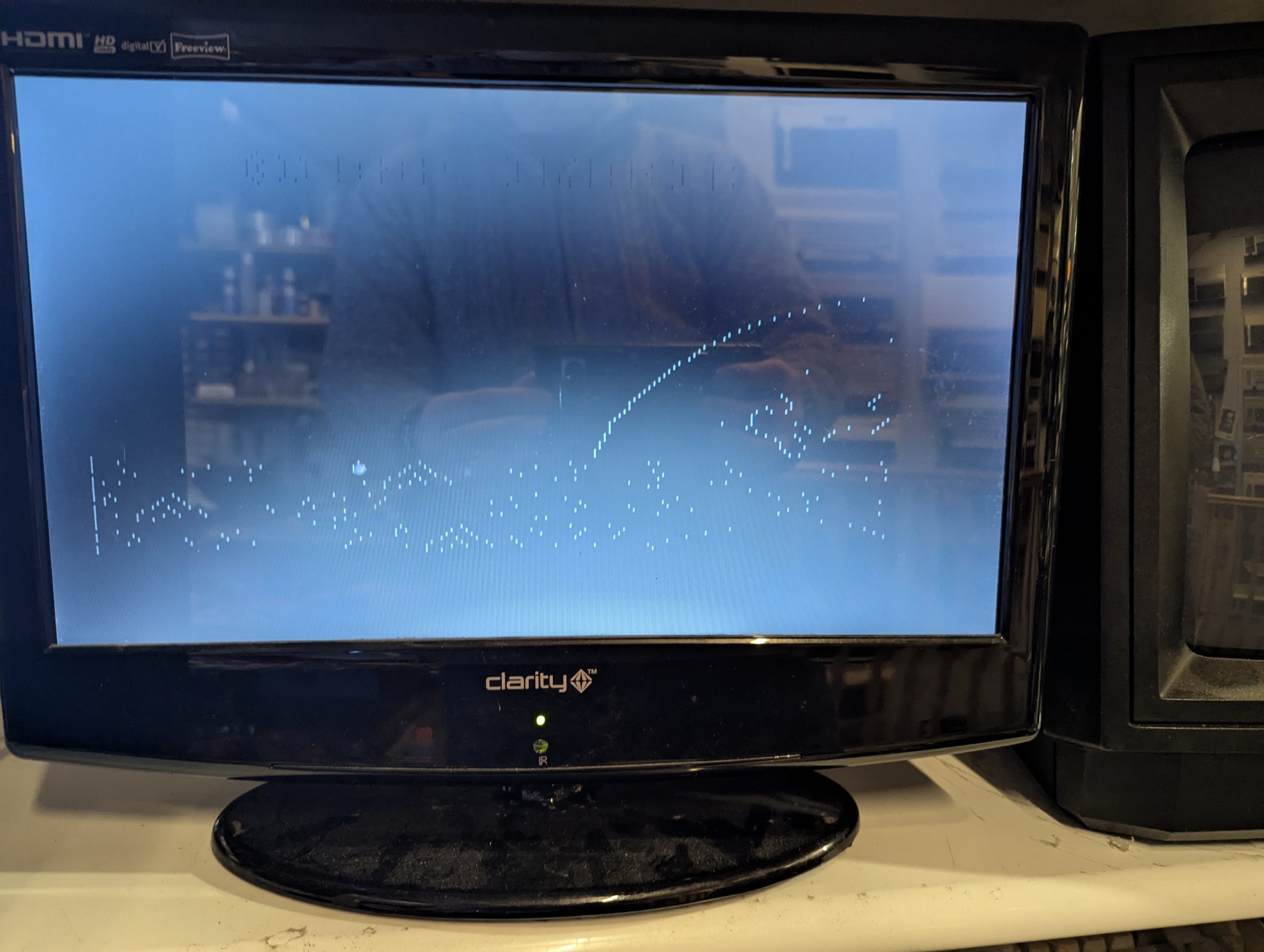
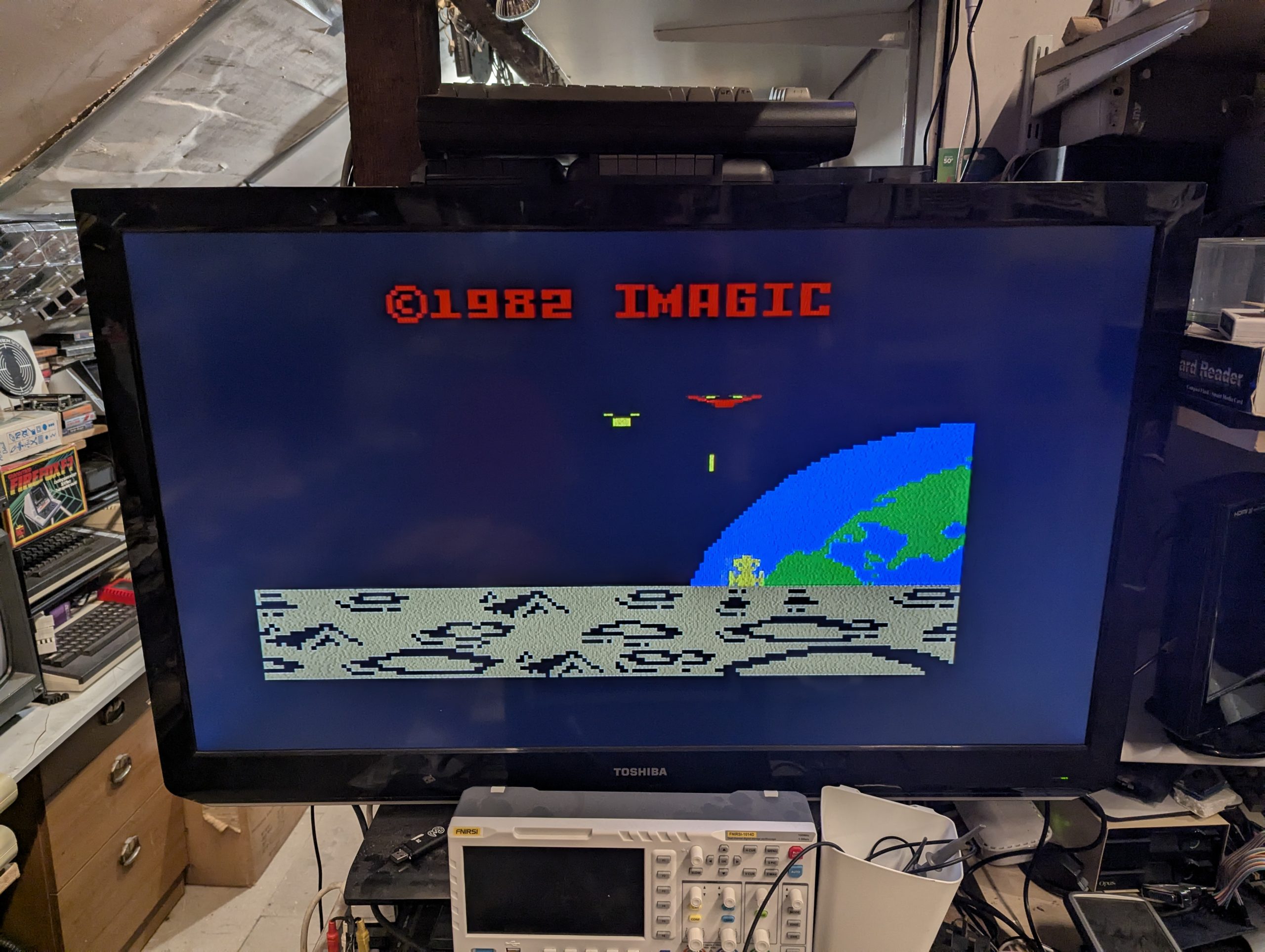
So there is a faint image but not quite the perfect quality RGB image that should be generated. Not sure if its the franken RGB board or some other issue.
I went through each output pin from the RGB Franken board with my oscilloscope and the RGB and sync signals all look fine.
Spent quite a bit of time checking and rechecking the Franken RGB board. I couldn’t figure out what was wrong so I got my Amstrad CPC 464 which has a RGB cable to scart so I could get a working reference of signals.
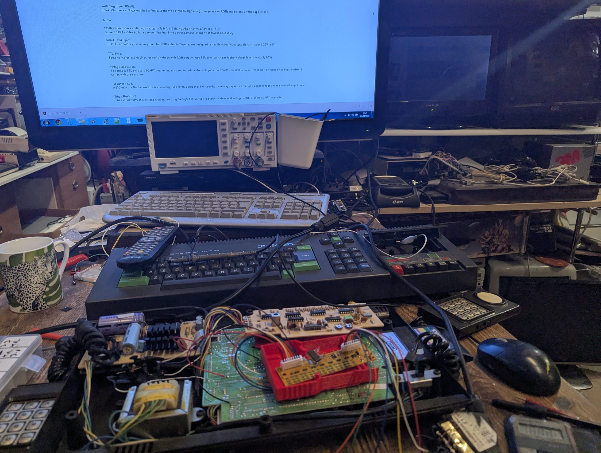
The RGB sync signals were alsmost exactly the same.
SCART
Time to look at some of the other Scart pins. The only other pins to consider are ground and pin 16 which is Fast Switching. I didn’t know much about this pin but I do now!. This pin expects 1-3V to set the TV to RGB mode. Any other voltage and composite mode is set. The supply voltage was 12v and the resistor I initially used got the voltage down to around 5v so testing with a few resistors got the voltage down to 1.2v. The final resistor was 1k ohm. The other resistor is on the sync line which starts at 5v which I thought was high so with a 3.3k gets the signal down to a normal <1v
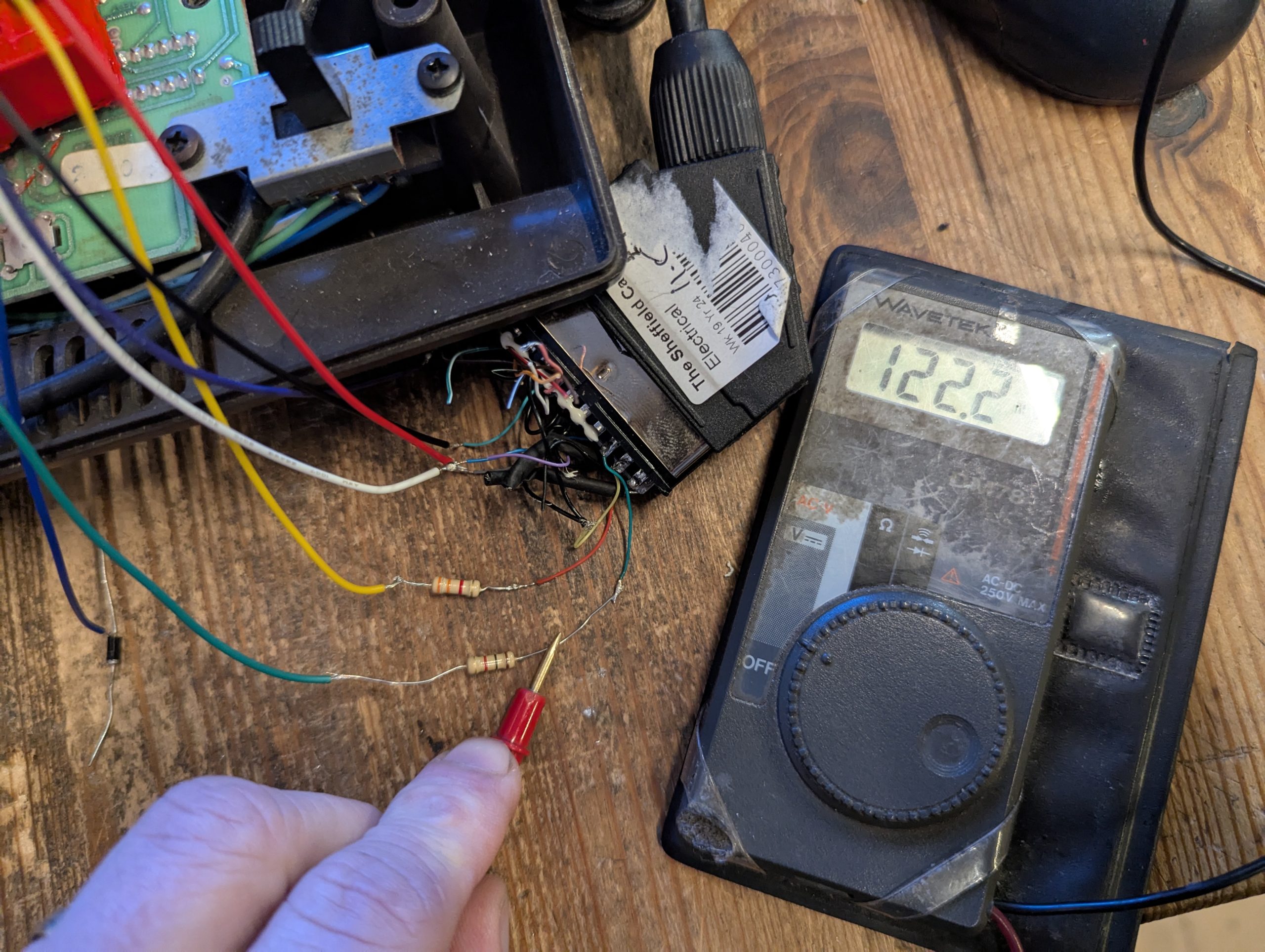
I know. The meter says 122.2v but I took the photo while it was settling down. I’ve had this multimeter for 40 years so its not the quickest and was in the process of moving the decimal point.
Anyway. Time for another test.
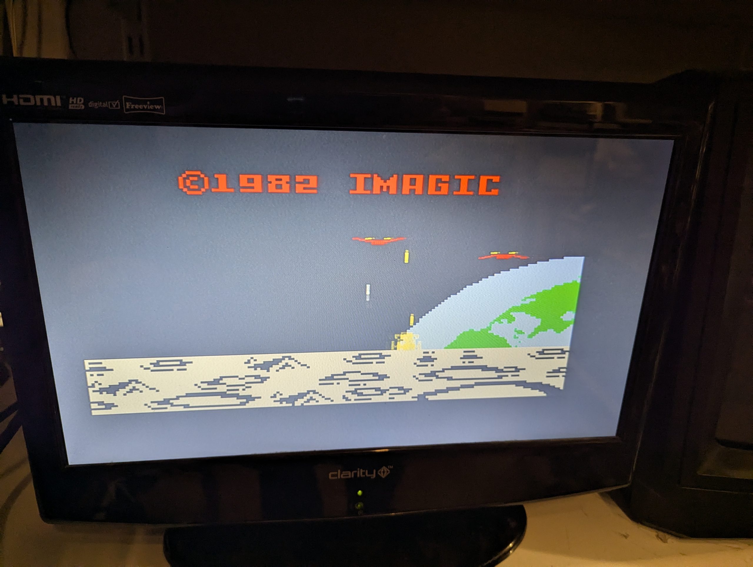
Now whats that word? oh yes EUREKA!. Finally! He shoots he scores. What a relief.
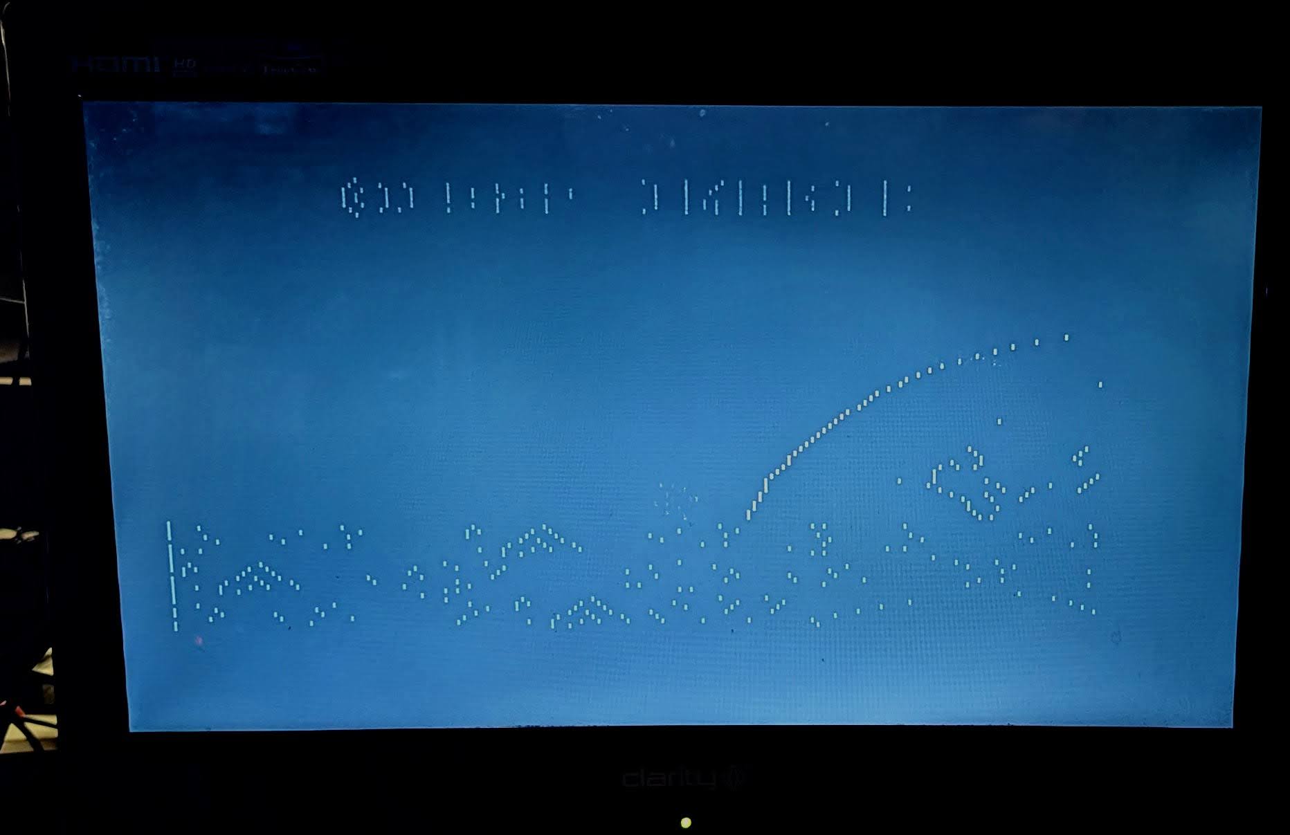
So the earlier black screen with white dots was where the Fast switching pin was receiving 5v and so was setting composite mode.
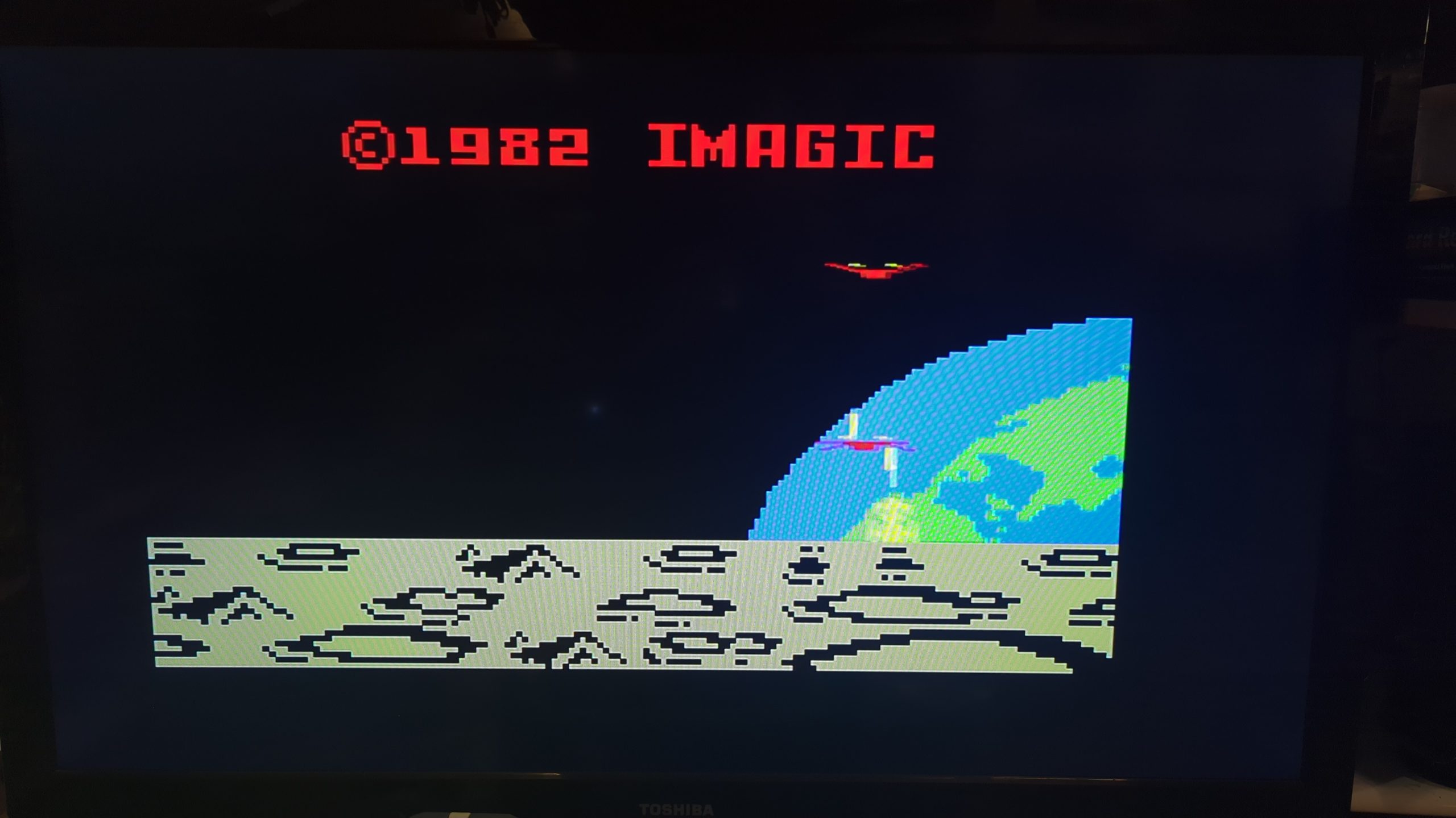
I still wasn’t happy with the RGB output but changing the Scart cable for a decent quality screened scart cable produced this.
This image doesn’t do justice to the real life TV output as the colours are crisp and solid with no scan lines or noise. It truly was a beautiful moment.
I tried altering all the settings on my mobile camera from shutter speed to various iso but the best I could get was the image below. I need to invest in a screen capture device.
Hats off to yannick and PCBway for producing a a great RGB board for the intellivision.
The correct parts finally arrived and so the Franken RGB board is no more.
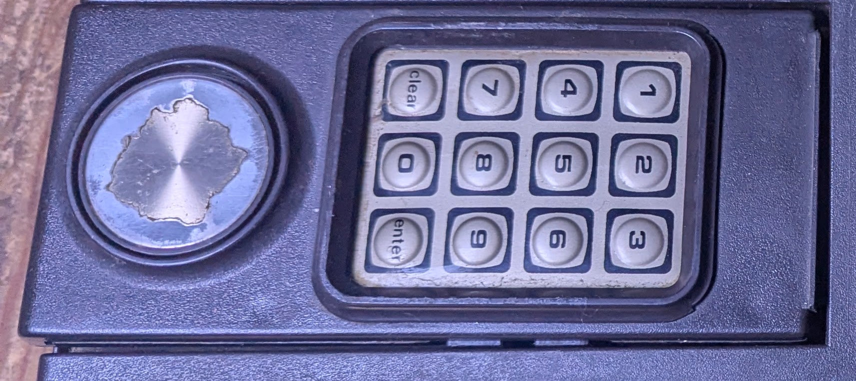
Controllers
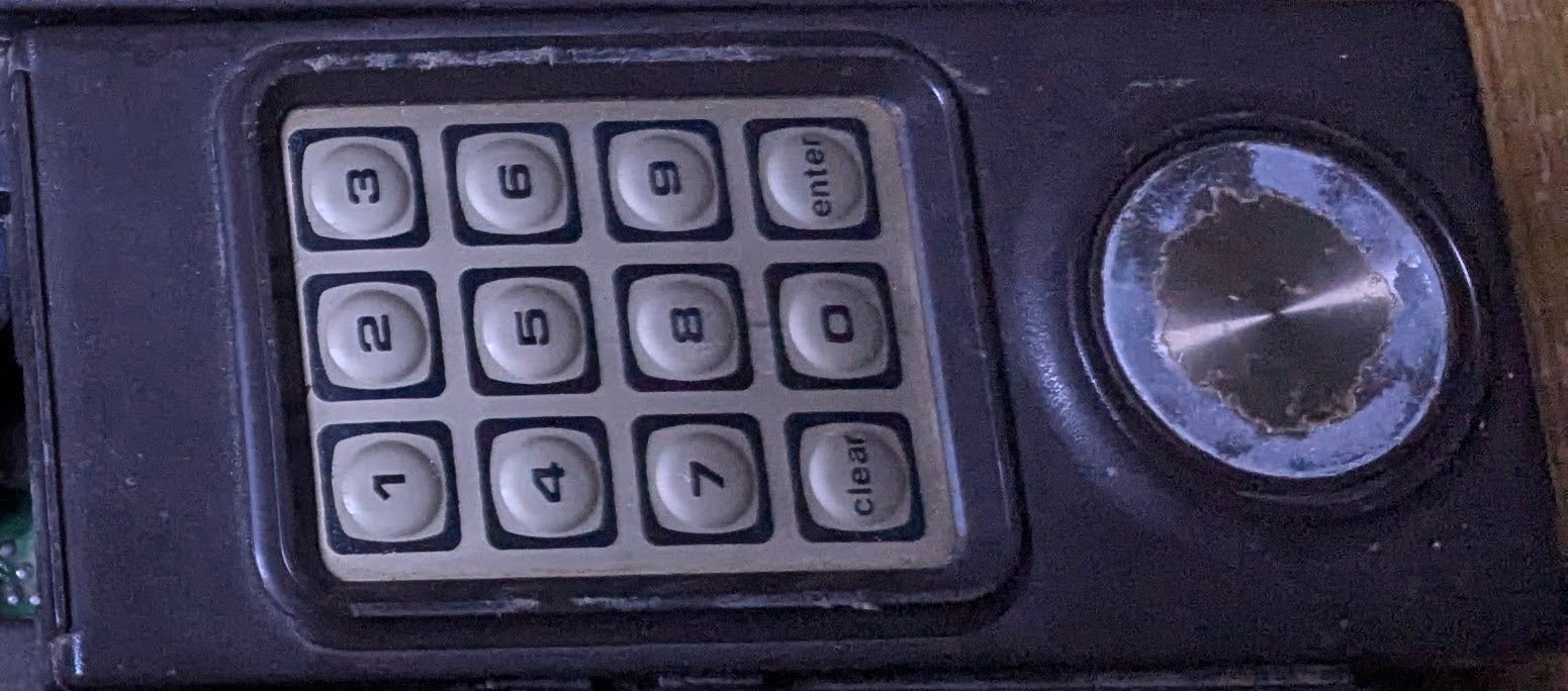
The controllers had seen some serious wear and were looking very tired
I was wondering if the discs could be salvaged
Er no.
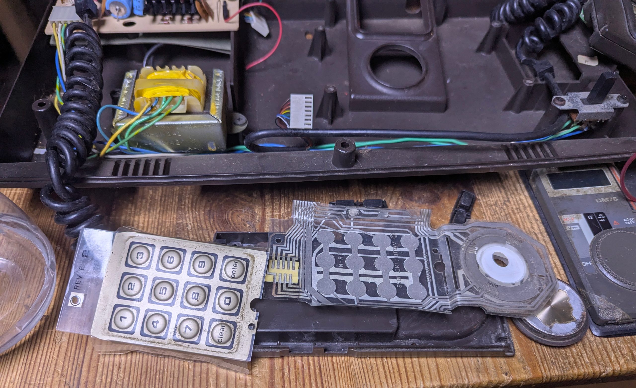
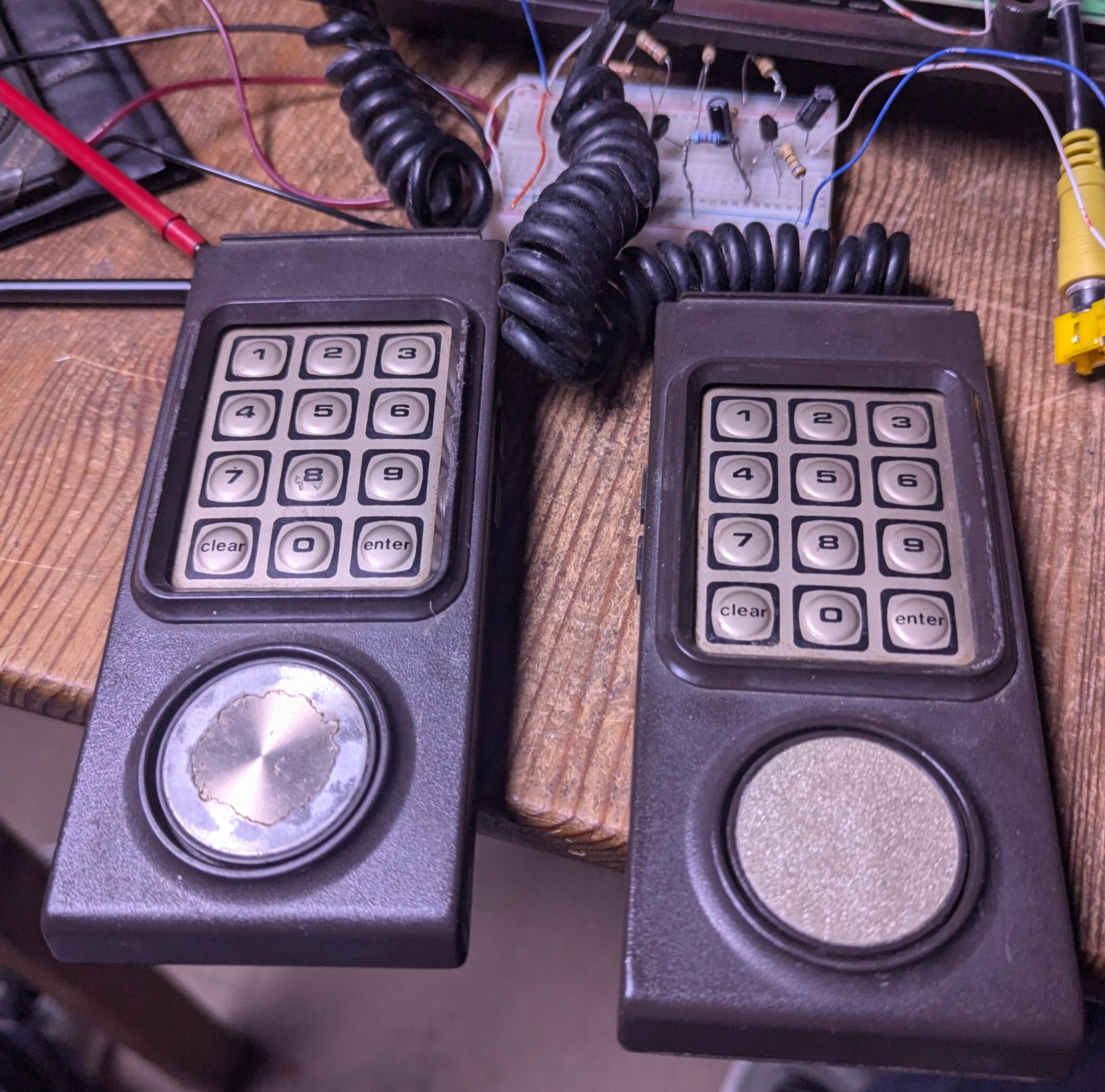
Decision made, I dismantled the controllers. Just 4 screws and they easily come apart. Just be careful as there is a sping and a plastic disc under the direction pad. There are three layers of membrane to keep track of so remember to replace them in order and to keep the plastic disc seperating the correct layers.
So the best option was to create some new discs. I tried various materials and settled on this which I think is a close match colour wise.
This Intellivision Video and Controller Upgrades project was a great learning curve with hotplate soldering, learning the intrecacies of Scart signals and RGB and sync signals.
So thats the end of another adventure.
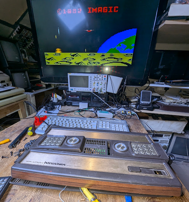
Now time for some games 🙂
Addendum
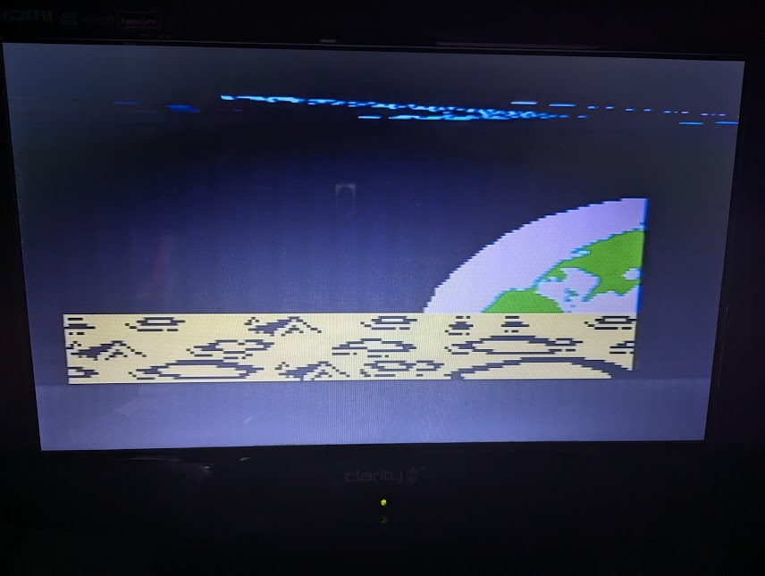
I was enjoying the game party for about 15 minutes when glitches began appearing on screen getting progressively worse as seen here. Damn it!.
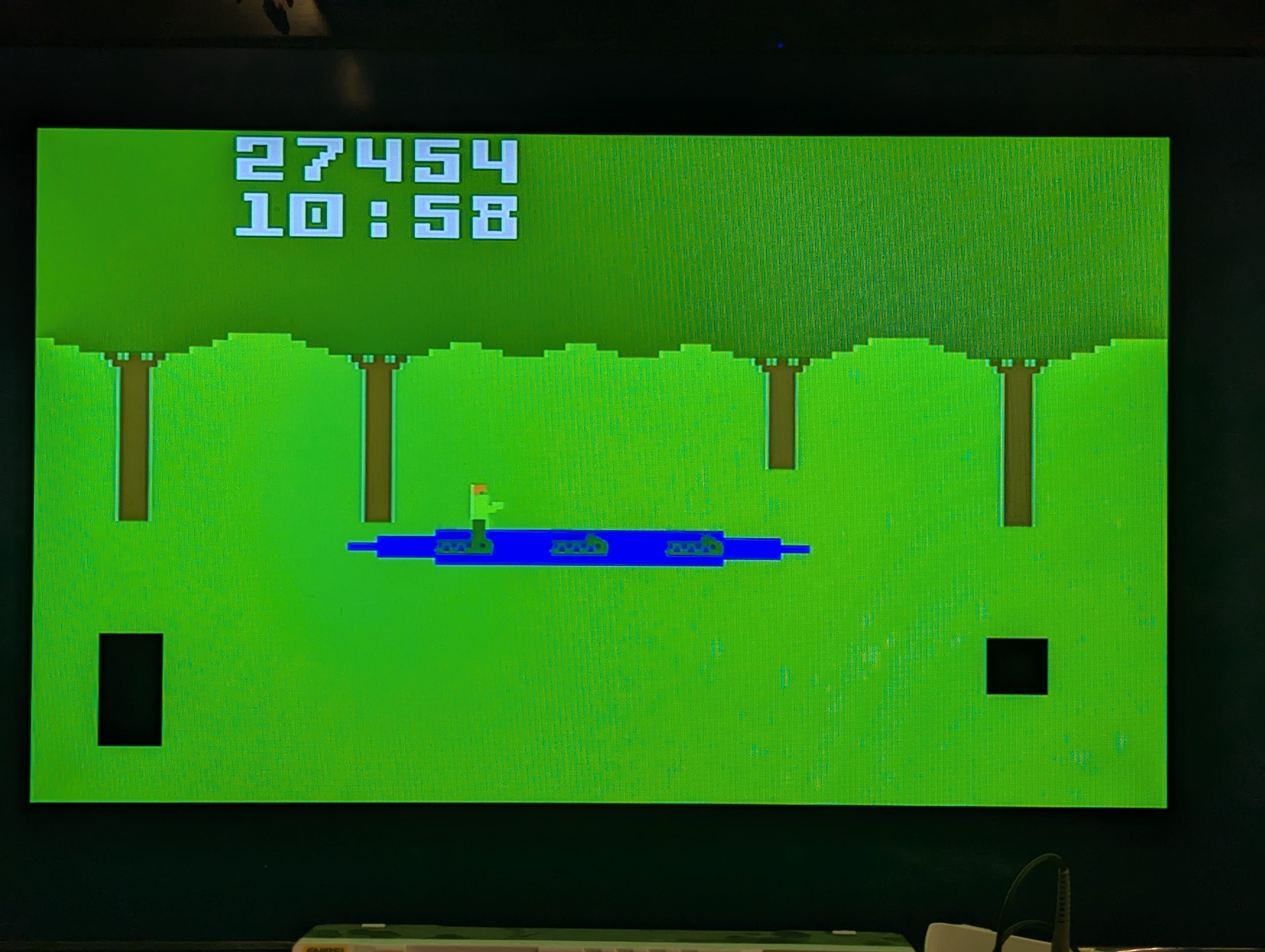
There was also regular occurrences of the screen going completely blank for a second and then returning to the glitchy screen.
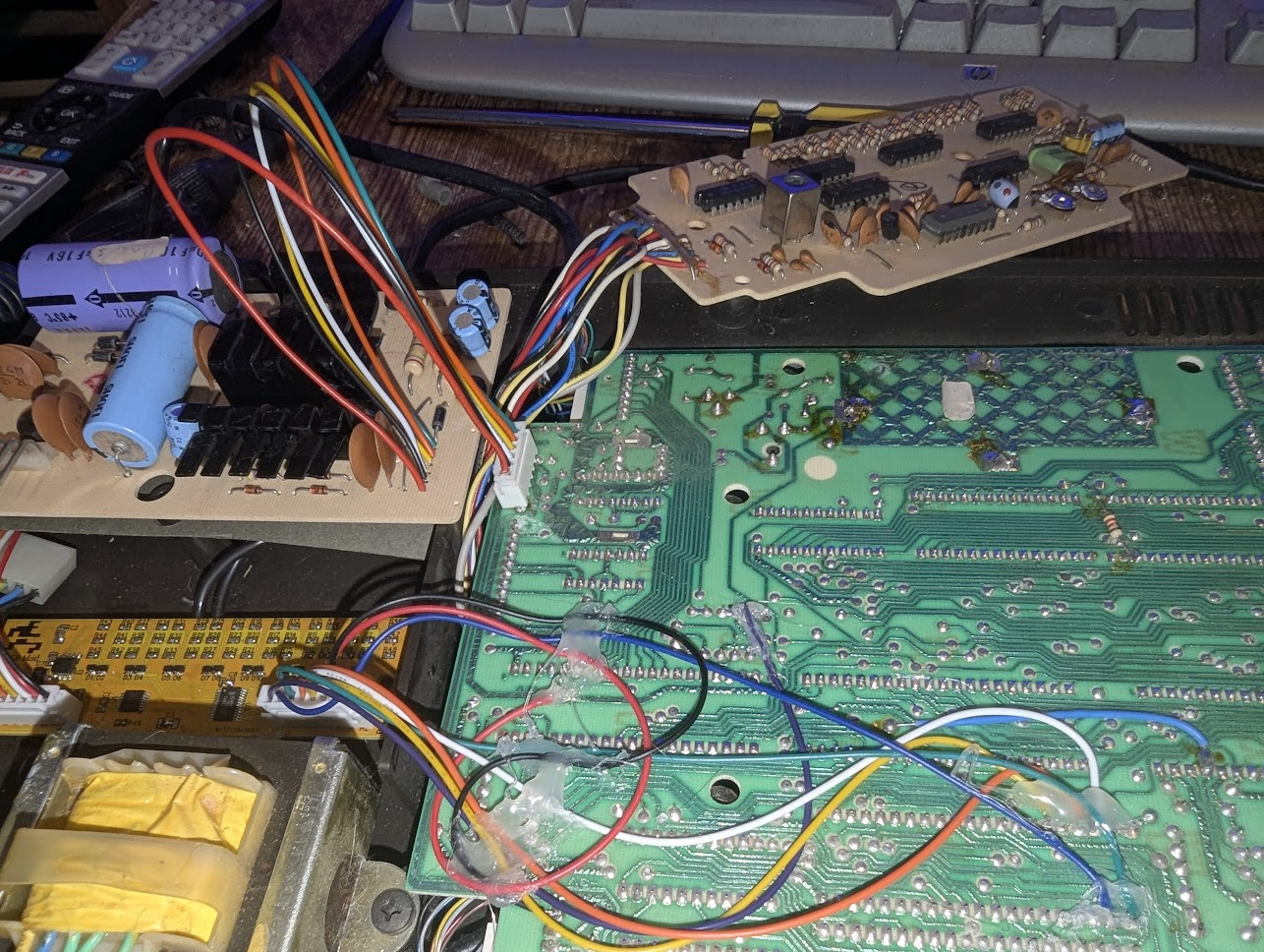
I immediately suspect my new wiring but after wiggling each wire there was no improvement.
Letting the console cool down then power up resulted in the same. 15 minutes and the glitching would return.
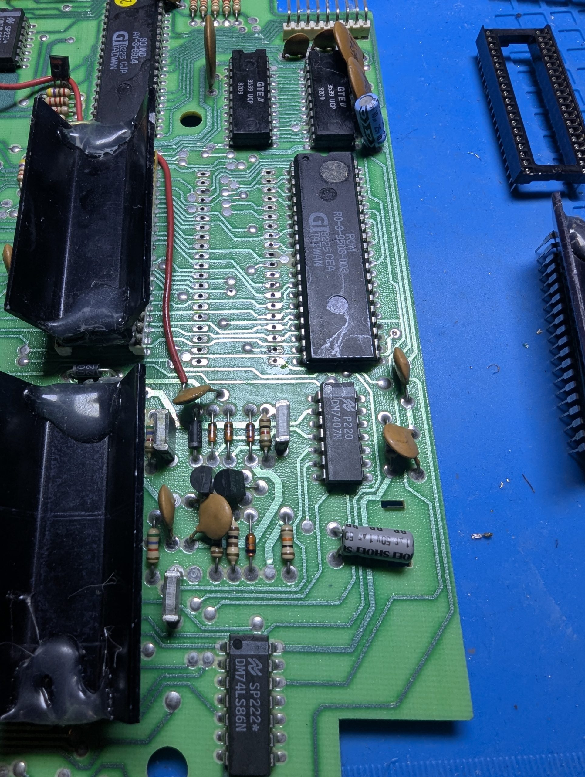
I tested all the capacitors and they were fine so I began tapping around the motherboard suspecting a dry joint. This began to reveal something. Tapping around the STIC area was definitely where the problem was. I hope the STIC hasn’t failed as that would be game over.
I decided to reseat the socketed chips and discovered this.

The STIC socket was missing a piece but also had distorted probably due to the heat. Time to replace.
That’s better. Resoldered the RGB mods and all is well. Tested for about an hour and no issues.
Forgot to mention I replaced the power boardv ribbon connector which is a common point of failure and worth doing for the longevity of the Intellivision.
Finally done!.
I’ll probably put this up for sale once I’ve finished play testing 😉
Click here for the Intellivision DIY Multicart