Introduction
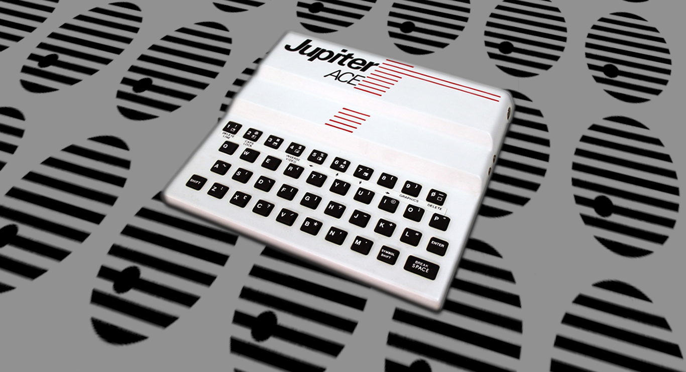
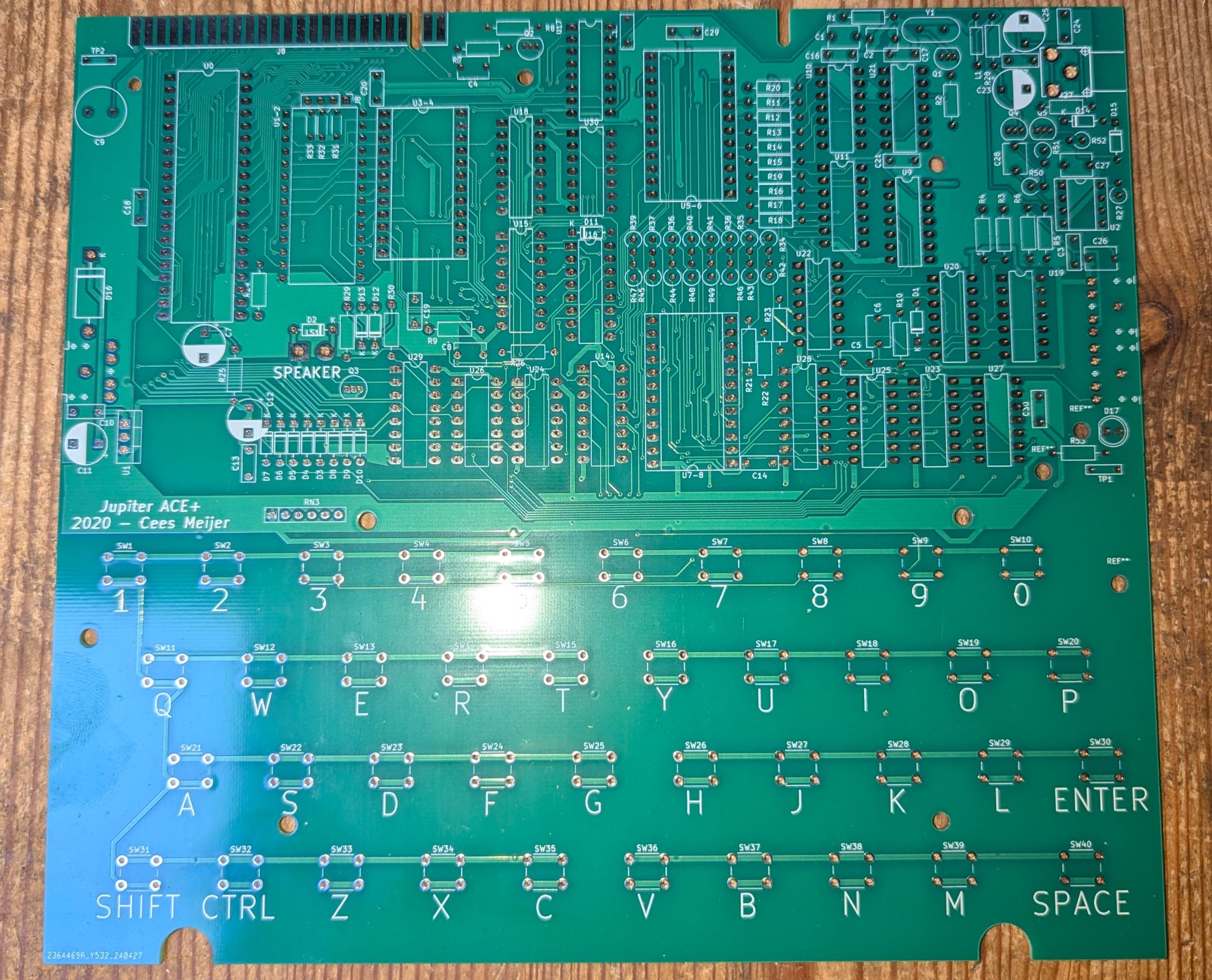
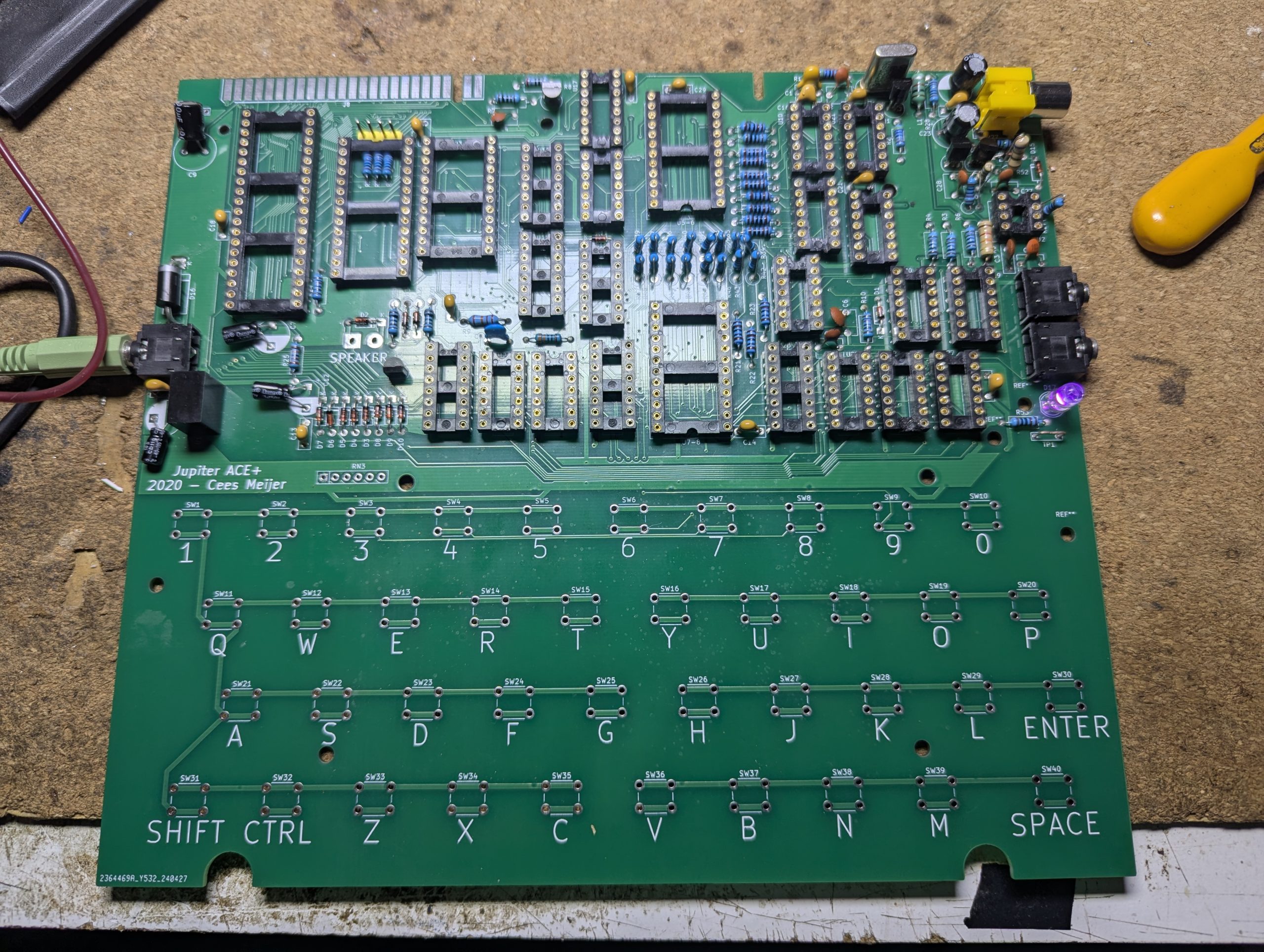
Building a Jupiter Ace. Not a very exciting computer back in the day as the Sinclair ZX Spectrum came out around the same time with its colour screen and plethora of games but the Jupiter Ace always fascinated me with its native FORTH language as opposed to the usual BASIC. So flash forward a few decades and what was a £89.99 computer now sells for an eye watering £1400!! on ebay. As luck would have it I was recently provided the next best thing. A Jupiter Ace Clone or at least the motherboard, provided by my good friend Dave. Sadly no other instructions just the board but thats all part of the fun. A big clue is It was designed by Cees Meijer in 2020. So here is the write up.
The Jupiter Ace orginally built by Jupiter Cantab is a 8bit computer release in 1982. Although not very popular back then it is now a very expensive and sought after retro.
Where to Start?
Looking at the board I could see I would need a lot of components. Some were obvious but many were not. I could see push buttons for the keyboard, sockets for chips, capacitors, resistors, diodes which were all push through soldering which was nice but it was obvious I needed a bill of materials or BOM. A bit of searching revealed a few great resources such as Cees Meijer obviously, Dr. Scott Baker, Jupiter Ace Archive, forum.tlienhard.com, but the BOM was the finally found here which is where Cees Meijer later moved the project to. There were also many other useful things such as schematics, 3D print files for the case and keys, logos but the big plus was the troubleshooting for when things go wrong, which they inevitably will.
BOM
Here is the list. Fortunately I had quite a few of these already.
Designator,Package,Quantity,Designation,Supplier and ref,Column1,_1
U1-2,DIP-28_W15.24mm,1,27C512,,, ** Got
U2,DIP-8_W7.62mm_Socket,1,NE555,,, ** Got
“U11,U9,U10”,DIP-14_W7.62mm_LongPads,3,74LS393,,,** AliExpress Ordered 31/1/2025
“U7-8,U5-6,U3-4”,DIP-28_W15.24mm,3,HT6116 / HM6116 PDIP28,,, ** AliExpress Ordered 29/1/2025
“U14,U17,U15,U16,U18”,DIP-16_W7.62mm_LongPads,5,74LS367,,, ** AliExpress Ordered 29/1/2025
“U21,U22”,DIP-14_W7.62mm_LongPads,2,74LS11,,, ** AliExpress Ordered 29/1/2025
“U24,U25”,DIP-14_W7.62mm_LongPads,2,74LS02,,, ** AliExpress Ordered 29/1/2025
U26,DIP-14_W7.62mm_LongPads,1,74LS32,,, ** AliExpress Ordered 29/1/2025
U29,DIP-16_W7.62mm_LongPads,1,74LS138,,, **Got
U0,DIP-40_W15.24mm_LongPads,1,Z80CPU,,, **Got
U19,DIP-14_W7.62mm_LongPads,1,74LS00,,, ** AliExpress Ordered 17/02/2025
U28,DIP-16_W7.62mm_LongPads,1,74LS166,,, ** AliExpress Ordered 29/1/2025
U27,DIP-14_W7.62mm_LongPads,1,74LS74,,, ** AliExpress Ordered 29/1/2025
U23,DIP-14_W7.62mm_LongPads,1,74LS86,,, ** Got
U20,DIP-14_W7.62mm_LongPads,1,74LS08,,, ** AliExpress Ordered 29/1/2025
U30,DIP-14_W7.62mm_LongPads,1,74LS04,,, ** AliExpress Ordered 31/1/2025 Got
“R34,R35,R36,R37,R38,R39,R40,R41,R42,R43,R44,R45,R46,R47,R48,R49”,R_Axial_DIN0309_L9.0mm_D3.2mm_P2.54mm_Vertical,16,1K0,,, ** AliExpress Ordered 29/1/2025
C1,C_Disc_D6.0mm_W4.4mm_P5.00mm,1,30p,,, **Got
C2,C_Disc_D6.0mm_W4.4mm_P5.00mm,1,100p,,, **Got
C3,C_Disc_D7.0mm_W2.5mm_P5.00mm,1,47n,,, **Got
“C4,C5”,C_Disc_D6.0mm_W4.4mm_P5.00mm,2,47p,,, **Got
C6,C_Disc_D6.0mm_W4.4mm_P5.00mm,1,47n,,, **Got
“C7,C11,C12”,CP_Radial_D8.0mm_P5.00mm,3,1u,,, ** AliExpress Ordered 31/1/2025
C8,C_Disc_D6.0mm_W4.4mm_P5.00mm,1,2n2,,, **Got
C9,C_Radial_D10.0mm_H12.5mm_P5.00mm,1,100u,,, **Got
C10, C13, C14, Beside U17 is C15, C16 C17, C18, C19, C20, C21, C22 Likely behind Vid out, C24, C29,C30,C_Disc_D7.0mm_W2.5mm_P5.00mm,14,100n,,,
“C23,C25”,CP_Radial_D8.0mm_P5.00mm,2,100u,,, **Got
“D1,D2,D3,D4,D5,D6,D7,D8,D9,D10,D11,D12,D13,D14,D15”,D_DO35_SOD27_P7.62mm_Horizontal,15,
1N4148,https://www.sparkfun.com/products/8032,, ** Got
“J1,J2,J4”,AUDIO-JACK,3,Low profile 3.5mm stereo audio jack. 5 contacts.,,, ** AliExpress Ordered 1/2/2025
L1,L_Axial_L5.3mm_D2.2mm_P10.16mm_Horizontal_Vishay_IM-1,1,L 1mH
LS1,SolderWirePad_1x02_P5.08mm_Drill1.5mm,1,Speaker- K 28 WP – 50 Ohm,Visaton,, ** Got
Q1,TO-92_Inline,1,2N3904,,, ** Got
“Q3,Q4,Q5”,TO-92_Inline,4,2N2222,,, ** Got
Q2,TO-92_Inline,1,2N2369 or BS170 (FET)(Fit BS170 opposite way round) ** AliExpress Ordered 31/1/2025
“R1 47k,R2 470k”,R_Axial_DIN0207_L6.3mm_D2.5mm_P10.16mm_Horizontal,2,47K (R2 may have to be 470K or higher when using 74HC series),,, ** Got
“R3,R4,R7,R11,R12,R13,R14,R15,R16,R17,R18,R19,R20,R21,R22,R23,R53”,R_Axial_DIN0207_L6.3mm_D2.5mm_P10.16mm_Horizontal,17,1K0,,, **Got
R5,R_Axial_DIN0207_L6.3mm_D2.5mm_P10.16mm_Horizontal,1,12K,,, **Got
“R6,R29,R30”,R_Axial_DIN0207_L6.3mm_D2.5mm_P10.16mm_Horizontal,3,1K,,, ** AliExpress Ordered 31/1/2025
R8,R_Axial_DIN0207_L6.3mm_D2.5mm_P10.16mm_Horizontal,1,270R,,, **Got
R9,R_Axial_DIN0207_L6.3mm_D2.5mm_P10.16mm_Horizontal,1,22K,,, **Got
“R10,R24”,R_Axial_DIN0207_L6.3mm_D2.5mm_P10.16mm_Horizontal,2,10K,,, **Got
R25,R_Axial_DIN0207_L6.3mm_D2.5mm_P10.16mm_Horizontal,1,220K,,, ** AliExpress Ordered 31/1/2025
R26,R_Axial_DIN0207_L6.3mm_D2.5mm_P10.16mm_Horizontal,1,330R,,, **Got
R27,R_Axial_DIN0207_L6.3mm_D2.5mm_P10.16mm_Horizontal,1,100R,,, **Got
R28,R_Axial_DIN0207_L6.3mm_D2.5mm_P10.16mm_Horizontal,1,10R,,, **Got
RN3,R_Array_SIP6,1,”Network, 5 resistors, 1 common. Anything from 1K to 47K.”,,, Ordered Aliexpress 17/02/2025
SW1 … SW40,SW_PUSH_6mm_H5mm,40,1..10 A..Z,,, ** AliExpress Ordered 1/2/2025
U1,TO-220-3_Vertical,1,LM7805_TO220,,, ** Got
Y1,Crystal_HC49-4H_Vertical,1,CRYSTAL 6.5000MHZ 20PF TH,DigiKey X1055-ND,, ** Cricklewood Electronics 1/2/2025
J5,RCA,1,RCA Phono Jack,Switchcraft PJRAN1X1U01X,, ** AliExpress Ordered 1/2/2025
Under U1 “R31,R32,R33”,R_Axial_DIN0204_L3.6mm_D1.6mm_P5.08mm_Horizontal,3,10K,,,
J8,PinHeader_1x04_P2.54mm_Vertical,1,Conn_01x04_Male,,,
C26,C_Disc_D6.0mm_W4.4mm_P5.00mm,1,10n,,,
C27,C_Disc_D6.0mm_W4.4mm_P5.00mm,1,820pF,,,
C28,C_Disc_D6.0mm_W4.4mm_P5.00mm,1,82pF,,,
“R27,R50”,R_Axial_DIN0309_L9.0mm_D3.2mm_P2.54mm_Vertical,2,10K,,, **Got
R51,R_Axial_DIN0309_L9.0mm_D3.2mm_P2.54mm_Vertical,1,56E,,, **Got
R52,R_Axial_DIN0309_L9.0mm_D3.2mm_P2.54mm_Vertical,1,68E,,, ** Got
D16,D_DO-201_P15.24mm_Horizontal,1,1N5400,,, ** AliExpress Ordered 29/1/2025
“TP1,TP2”,TestPoint_Bridge_Pitch5.08mm_Drill0.7mm,2,TestPoint,,,
D17,LED_D5.0mm,1,LED,,, ** Got
I decided to risk using Aliexpress to keep costs down. My trusty TL866 programmer is very handy for testing the ram and logic chips and a component tester for checking everything else.
I also decided to order the silicon silent soft press push buttons which avoid the very clicky non responsive usual kind.
This site by Stephen Gillespie was also a useful resource.
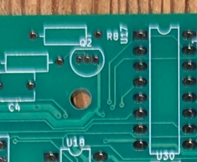
Note R53 is next to TP1. It’s not easy to read on the PCB. C15 is next to U17. Also, not easy to read
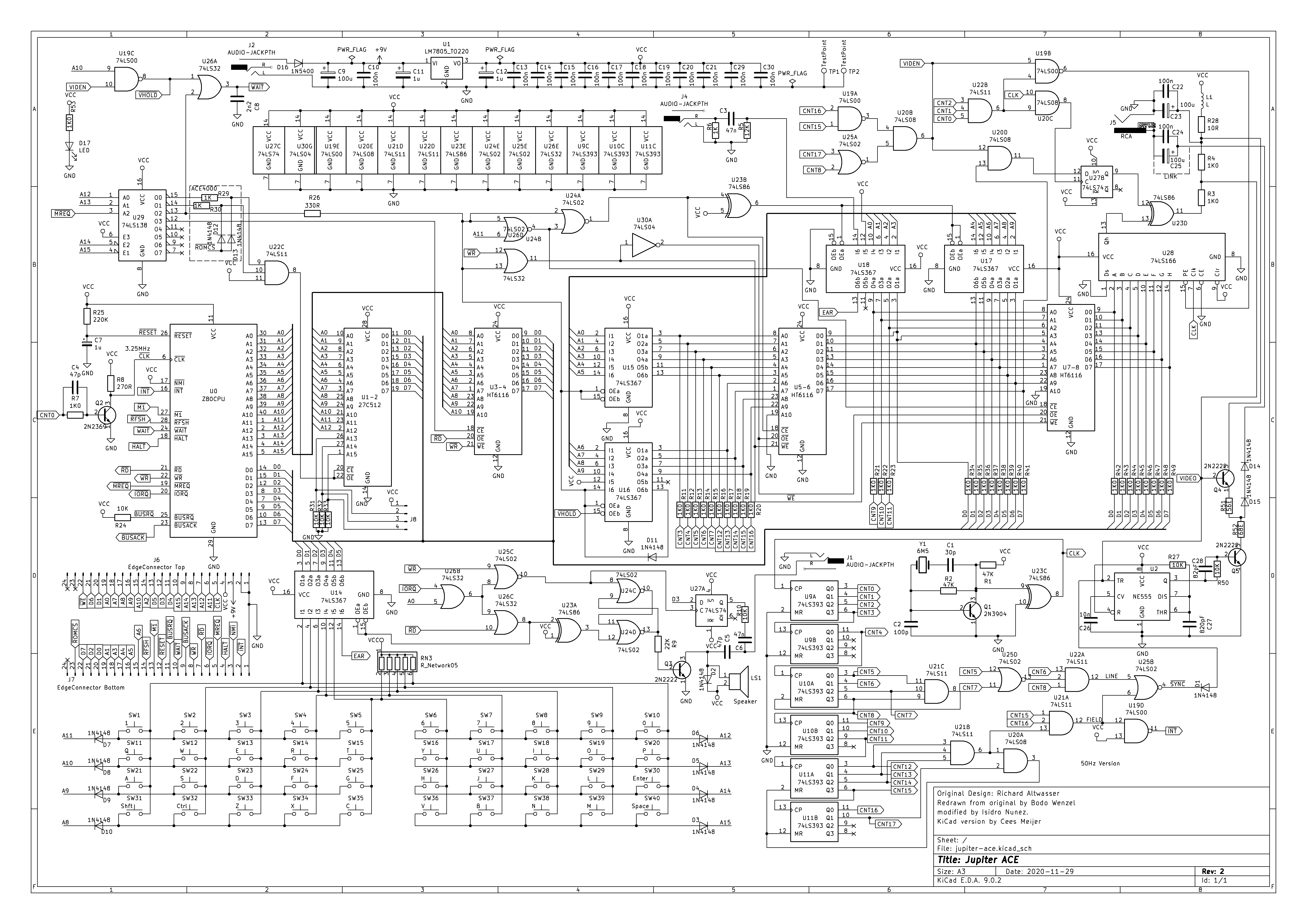
Here is the schematic for reference.
Construction
Since I had most of the sockets, resistors, diodes and a traco TSR 1-2450 voltage regulator I thought I would start soldering these while waiting for other parts. I marked off each added component on the BOM.
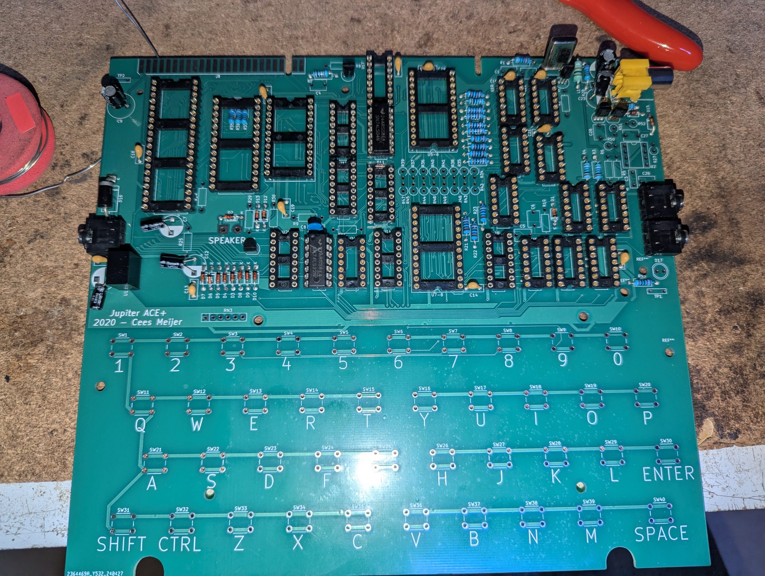
Eventually I got this far so it was time to check my work.
The polarity on the barrel plug is ground set to the tip and positive set on the sleeve. The contacts were not touching btw.
I used my bench supply which would highlight any short circuits safely. Set to 9v and its best to current regulate to approximatrly 340mA. If a short exists then check the underside of the board for any solder issues or flakes of solder / copper between tracks. Recheck the work as it will probably be something obvious at this stage. If not obvious then its probably a faulty component.
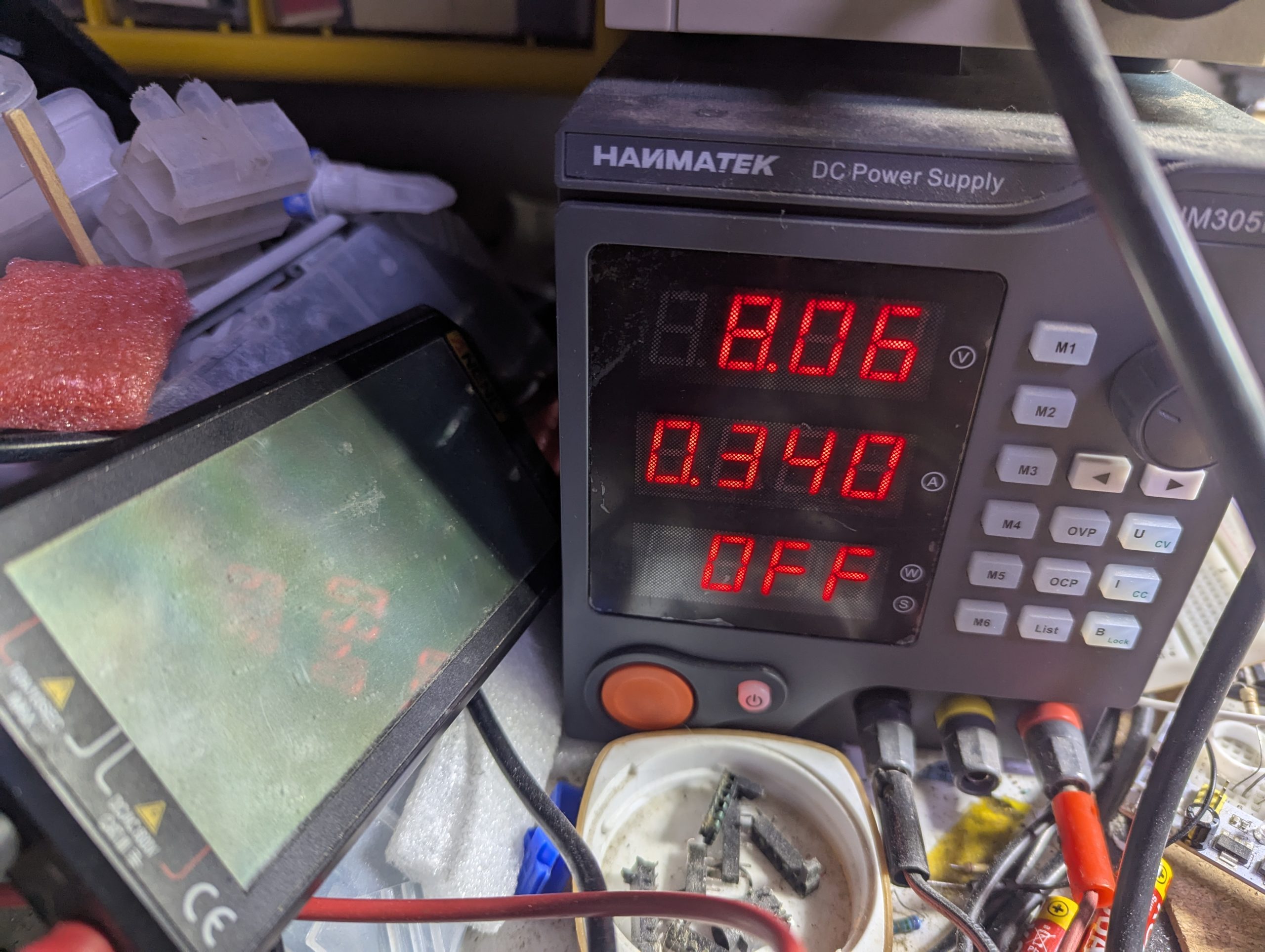
Not sure why I set 8v here but the voltage regulator was fine with it. Its safest to test without populating any sockets. You can also continuity test all the positive pins on the sockets before powering and also ensure there are no shorts to ground.
With the power supply on I didn’t get any short circuit message and no pops or smoke. So far so good.
Well at least the LED was wired correctly.
I tested each of the sockets for ground and an appropriate voltage of near 5v
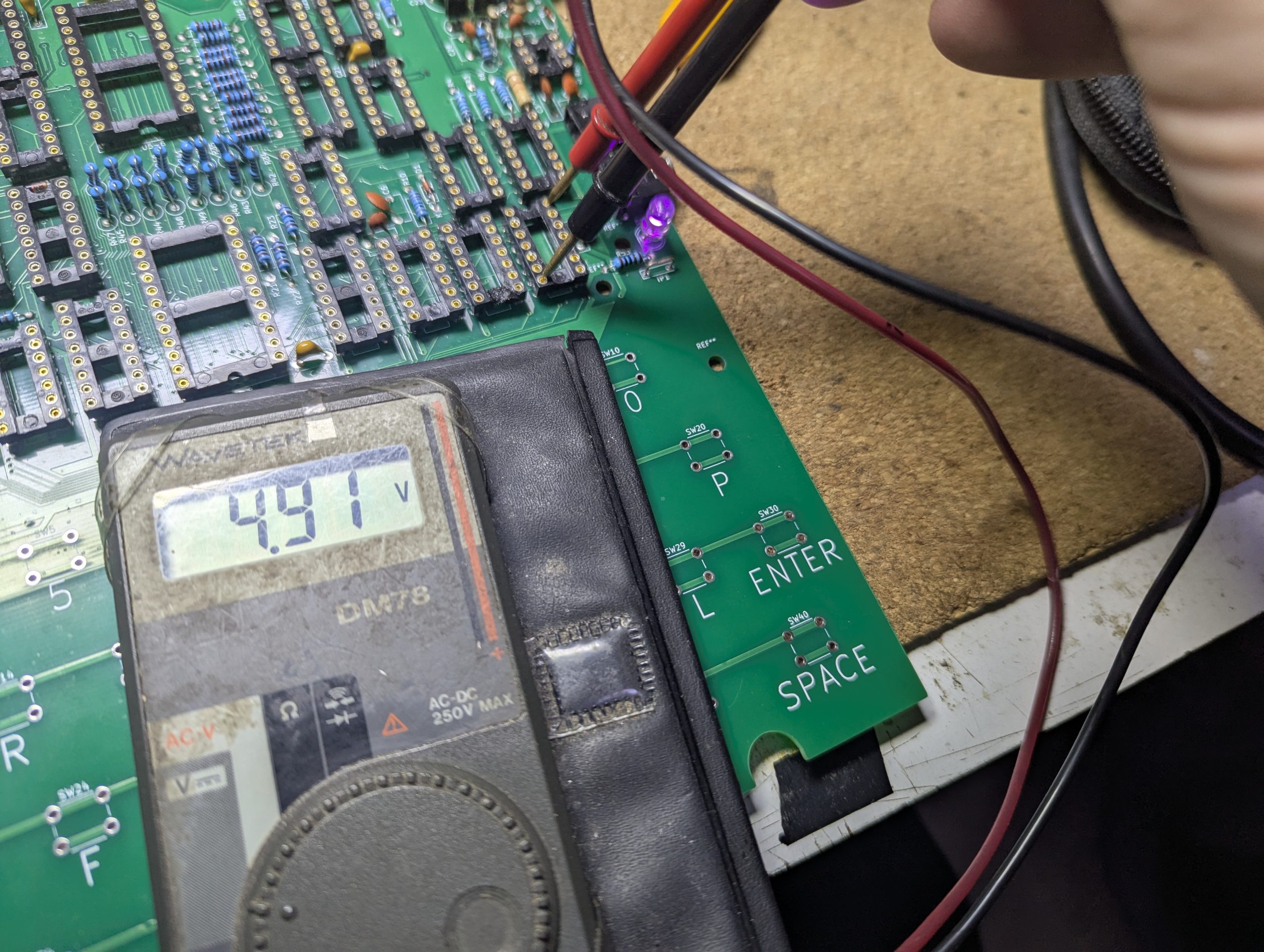
Thats all the voltages checked
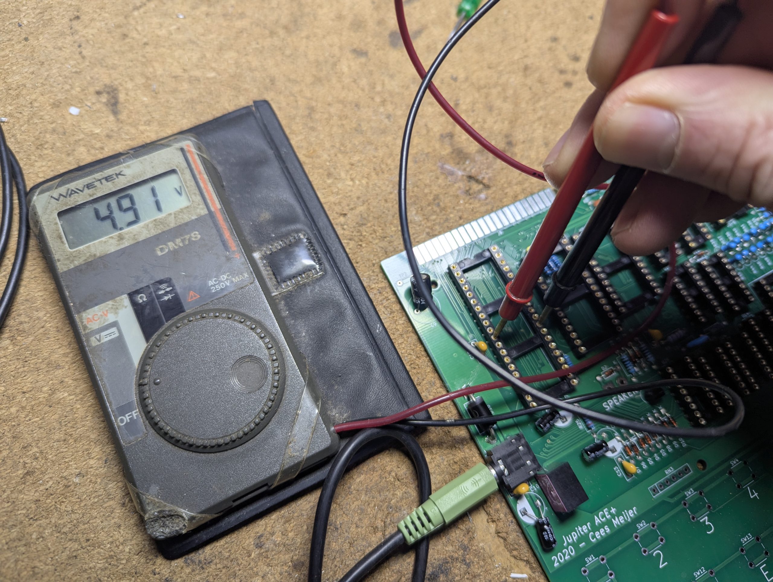
No shorts and good voltages where they should be. All grounds are in the right place too.
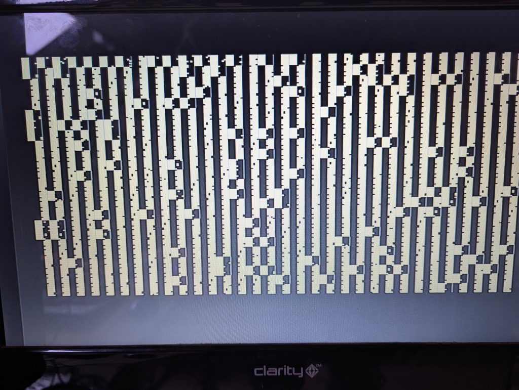
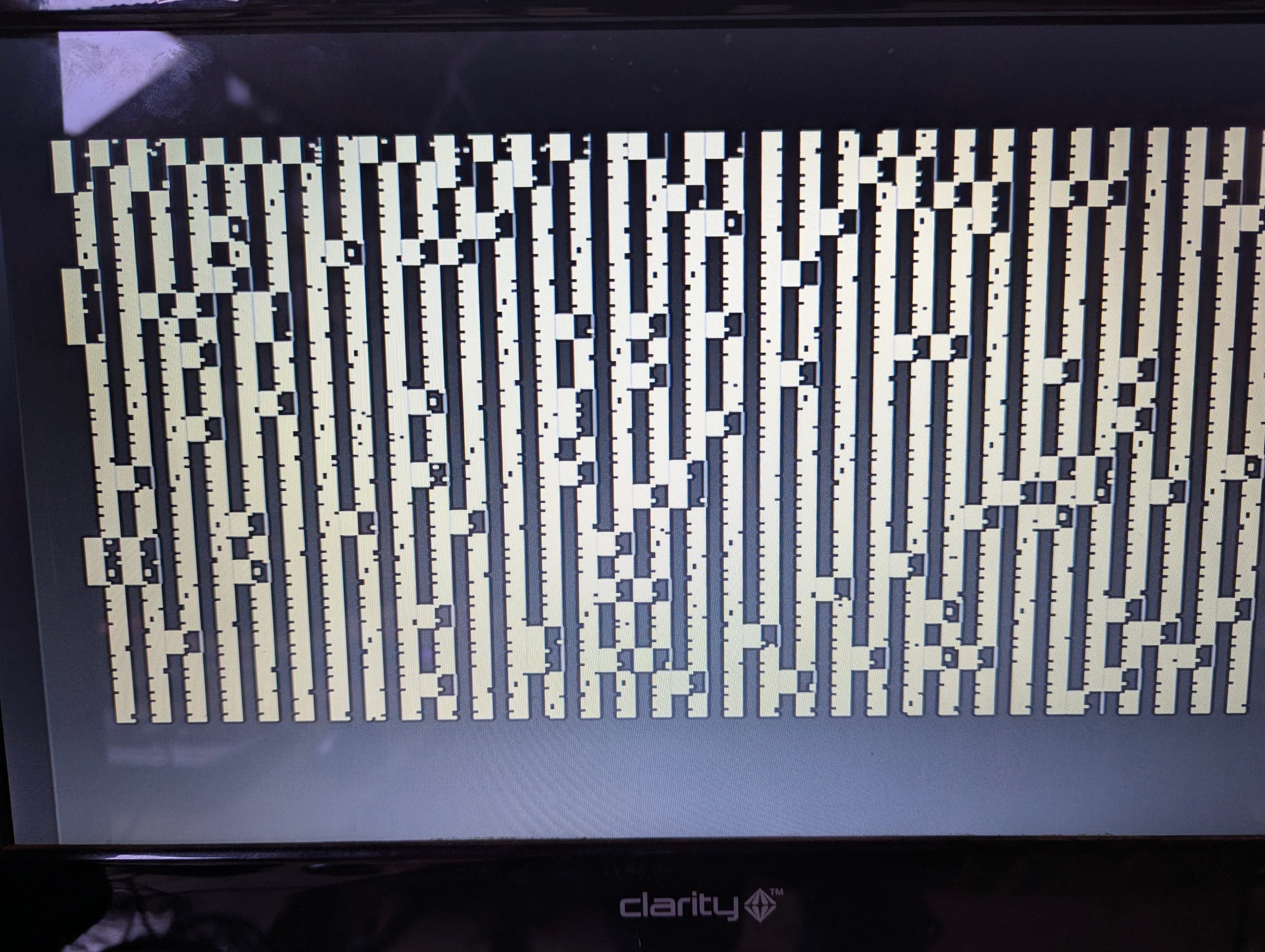
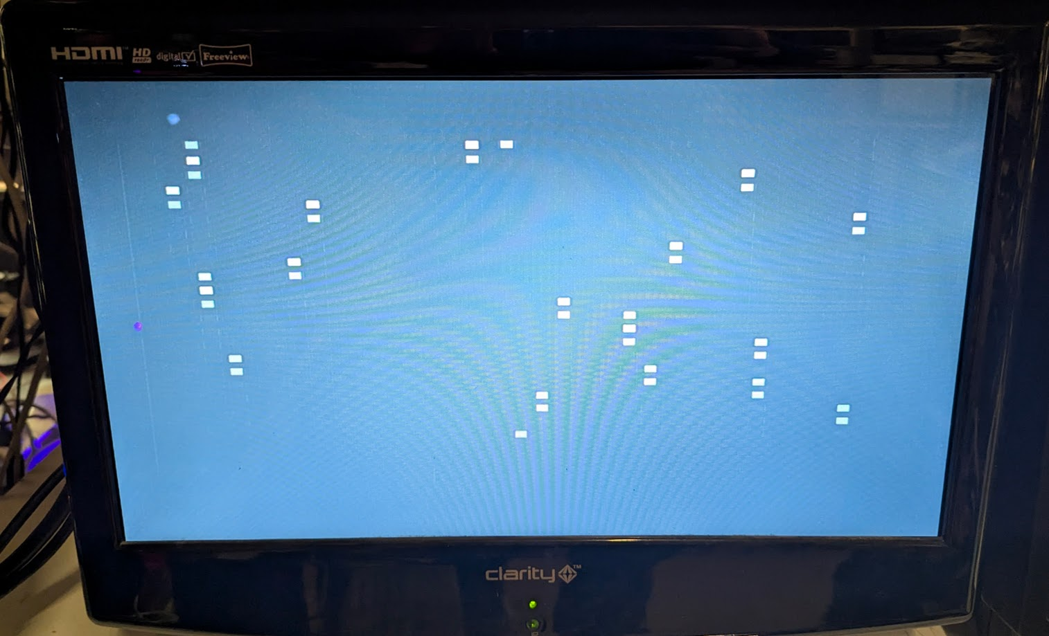
I first populated the logic chips and retested with power. All was good so tried the CPU and ram. I connected the monitor and powered up.
A garbage screen which was great news and expected as no rom was installed.
Making the ROM
I had a 27C512 however the rom file , available on the Jupiter Ace Archive , is 8k so my eprom would have plenty of space. To be safe I copied the rom file 8 times to fill the eprom.
copy /b ace.rom + ace.rom + ace.rom + ace.rom + ace.rom + ace.rom + ace.rom + ace.rom ace512.rom
The jumper J8 does not need any connections if using a 27C512. Join pins 1 and 4 for a 27c256 to set a15 to (vpp) 5v.
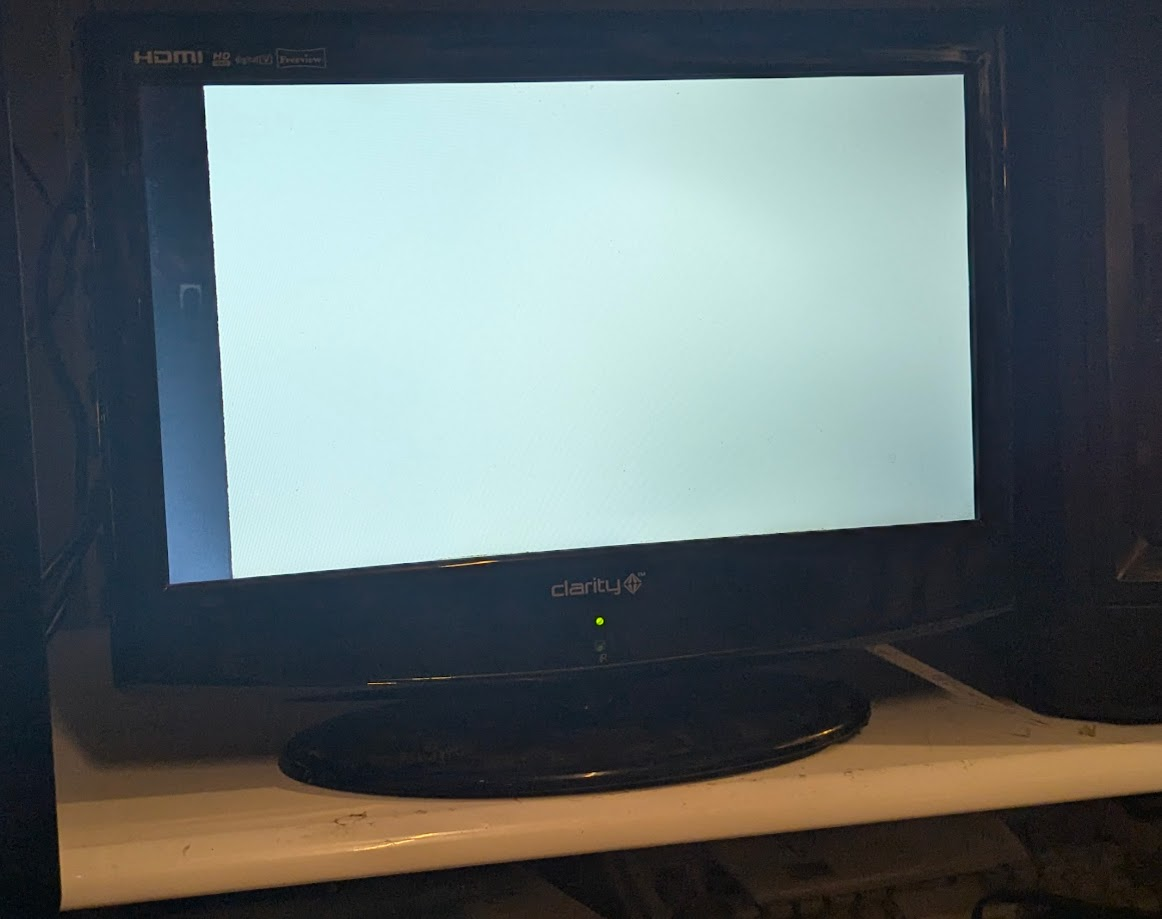
Programmed the file , turned on and…
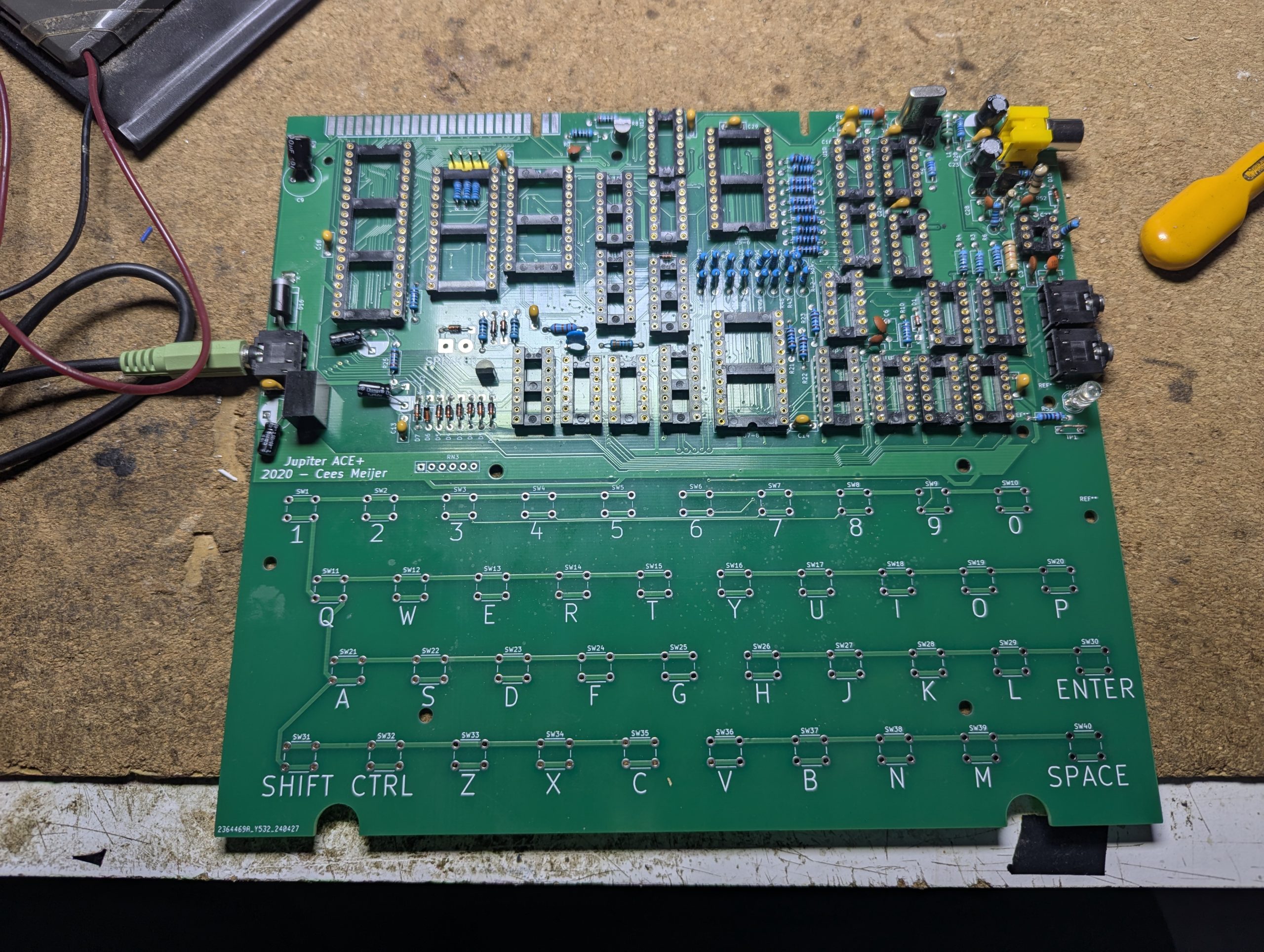
No matter what I try I get this screen. Even with the CPU and ROM removed. Reseated all the chips and checked all the voltages.
I thought the predator / thermal camera might reveal some clues which it did but I missed it. It was showing a reading on one of the transistors but I mistook it for a resistor heating up. I would regret that but I will trust the thermal camera more in future.
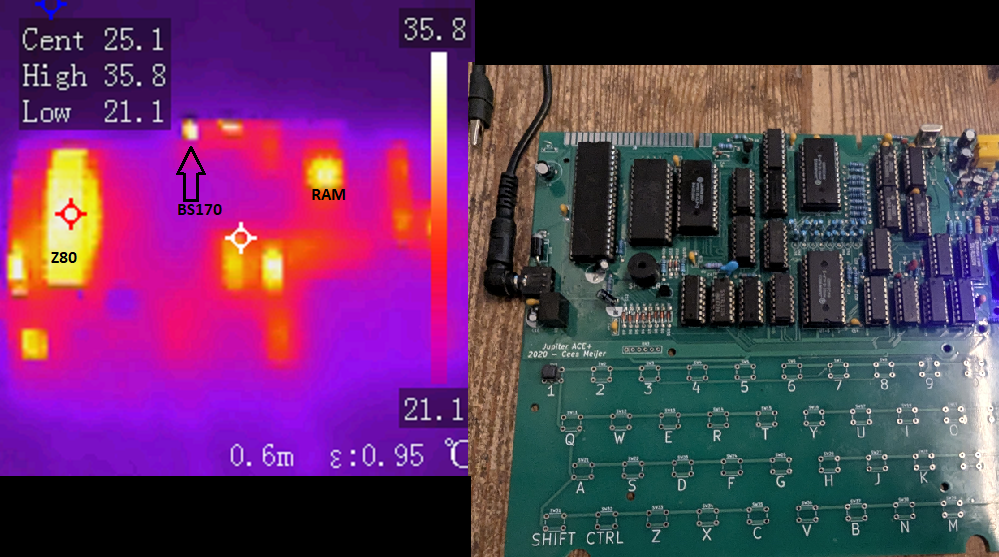
A 74LS32 also was getting slightly warm so I swapped it out but there was no change. One of the RAM chips was also slightly warmer but I didn’t have any replacements. I reseated it but no change so I thought it might be normal. The temperatures were not hot just warm so I decided to give it a rest as I was getting fed up.
A few weeks passed and I returned to it with new tests. I removed and checked the transistors which tested fine in the component tester but I noticed Q2 was a FET BS170 which is what I had at the time. The thermal camera had given a clue here. I now had the first choice in the BOM a 2N2369 NPN and so fitted it and…
Well , it was different to what I had been getting. What was wrong with the BS170 as it checked out ok earlier. Turns out its a FET and needs to be fitted inversely to the NPN 2N2369 so the solder mask was wrong for the FET transistor type but correct for a NPN.
So back to the white screen. I remember in my research something about a white screen. Removing the 555 timer may fix this.
I also decided to rotate the 3 ram chips as Scott Baker done when having issues with his build. See 10 minutes into his video here. Guess what? A black screen with no corruption!.
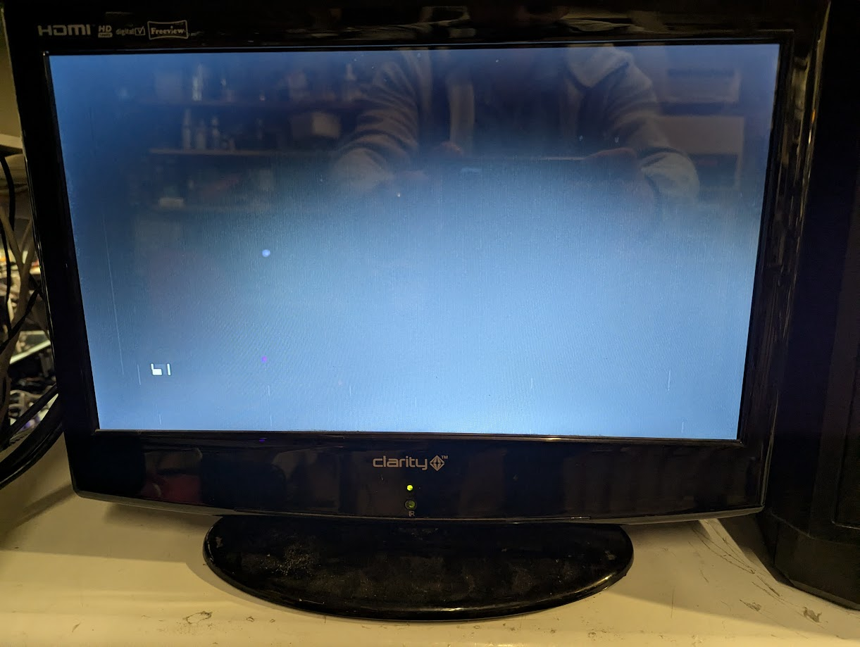
She works!. Now thats a Eureka moment. Well its a cursor at the very least. Lets add some keys and type something. However there was another issue.
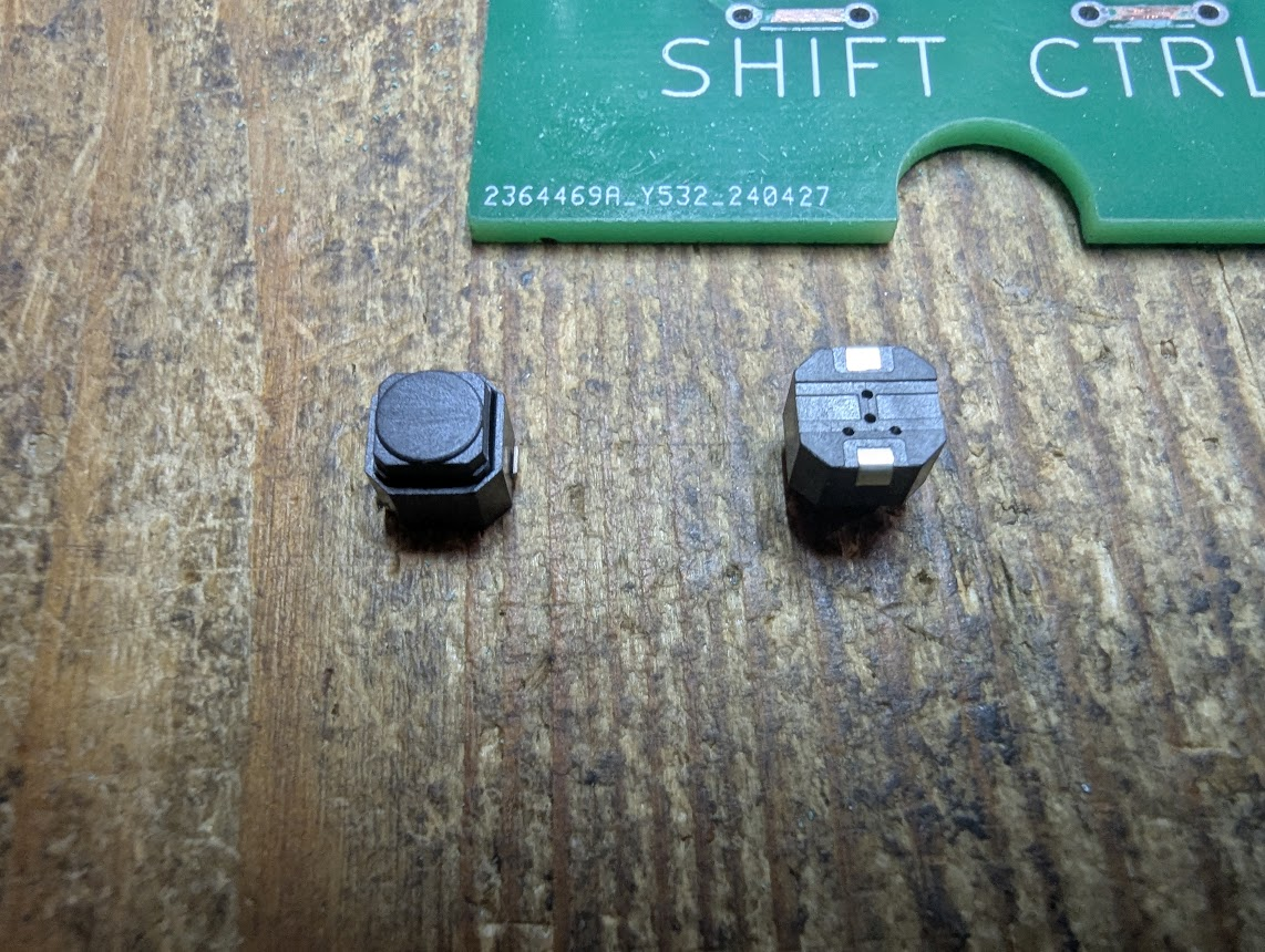
The push buttons I ordered were of the soft press type however they have two center vertical contacts and the board expects four corner contacts
A simple fix is to remove the solder mask which is across the pairs of contacts. This will allow placement of the keys exactly where they need to be. But there is an exception, of course there is!!. Inside No 9.
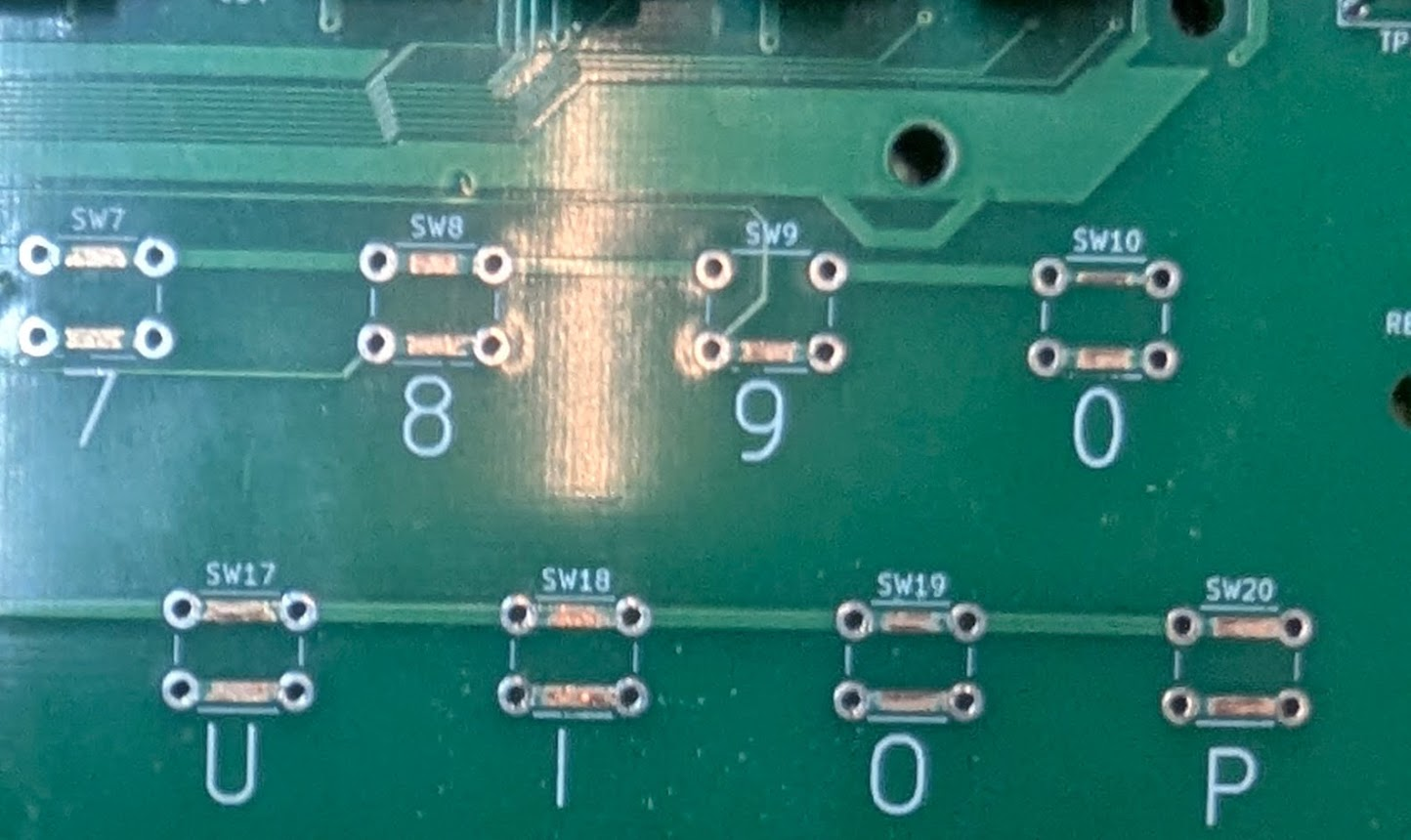
There is a trace going through its center and so has no masked out top trace like the others. I therefore decided to add some extra solder mask and just solder a trace over it.
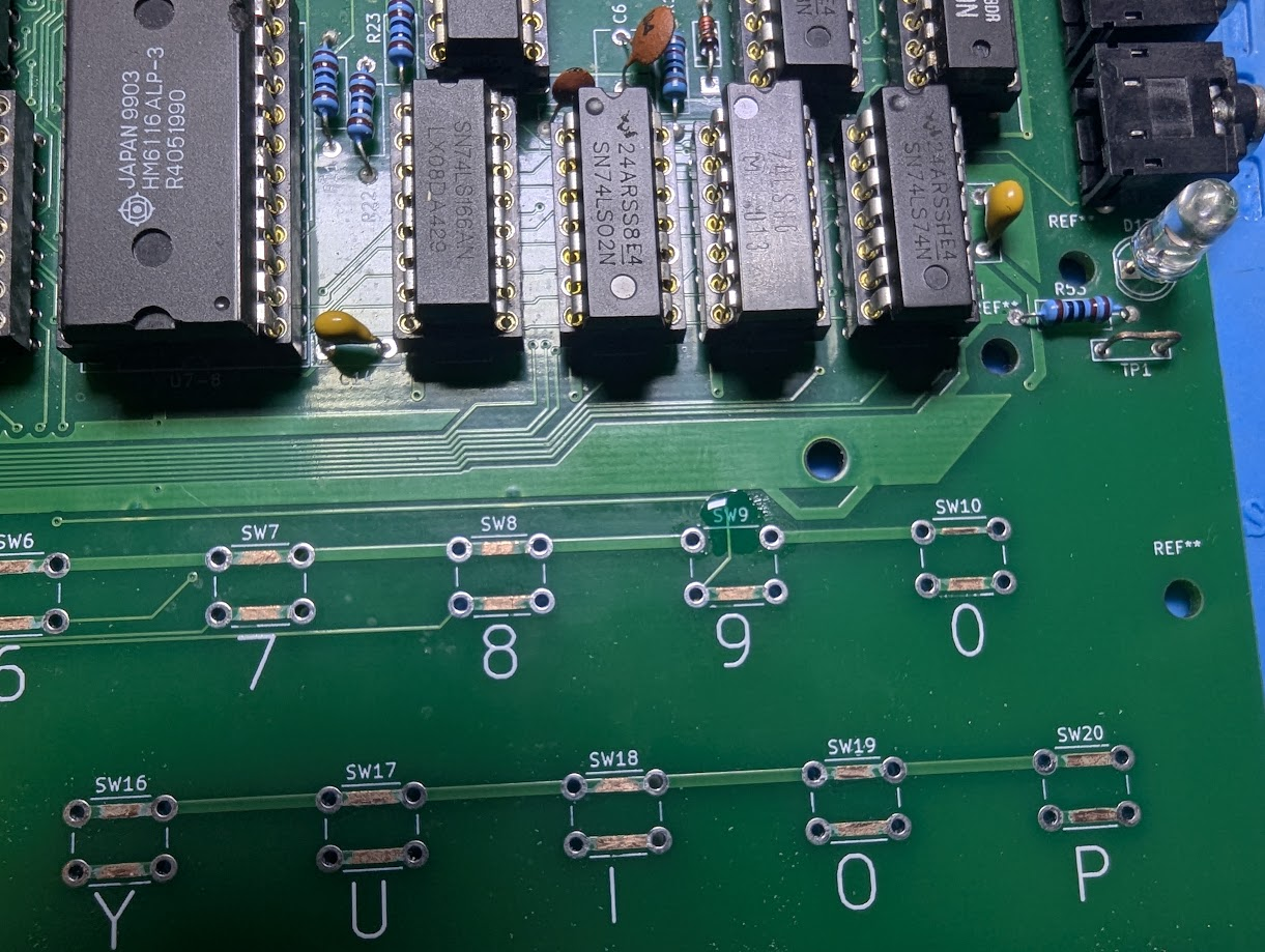
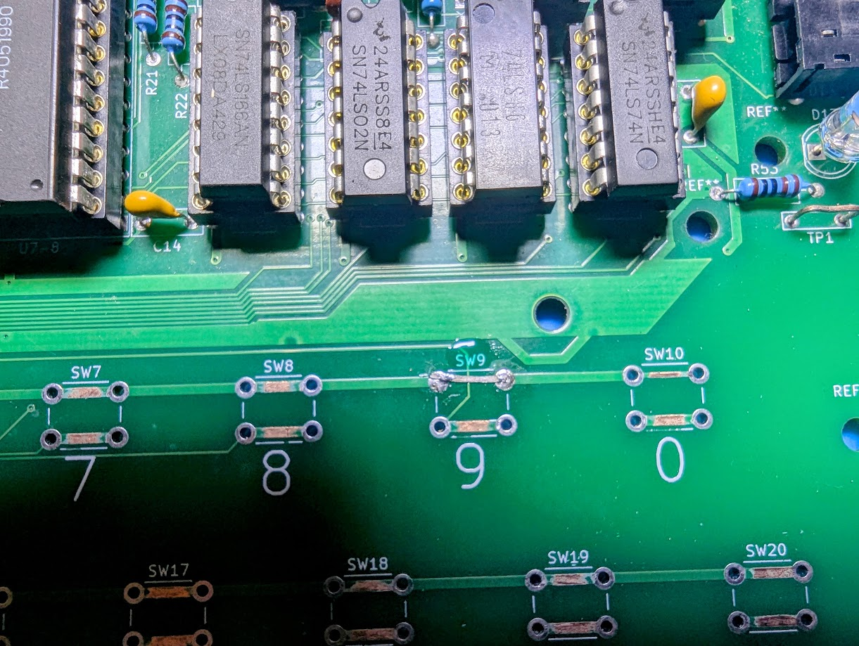
Plenty of solder at the corners and it will hold just as well as the others if not better.
I decided to just add a 1, 9, space and enter key.
Keyboard works!
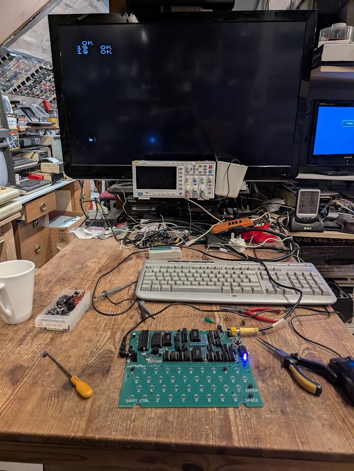
Ok thats enough of ‘Neh,neh,neh nineteen’. Its an old song by Paul Hardcastle for those too young or too old to remember :). The main thing is the keys are working. So time to finish the keyboard.
Troubleshooting
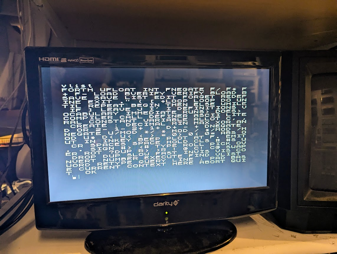
An annoying recurring issue is that sometimes I turn on the Ace there is a extra character somewhere on the screen or slight corruption of the cursor. When I enter a command such as ‘vlist’ I just get ‘list ok’ displayed at the top when a full list of commands should be displayed.
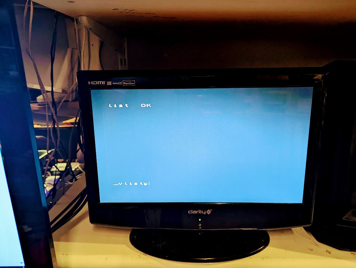
Rebooting does not fix this. This has been happening throughout this build and I’ve spent countless hours troubleshooting. I swapped all the HC logic chips for LS versions. Still didn’t fix it. I remembered an issue that Scott Baker had with the write enable signal arriving at the RAM chips before the address lines were latched. This was solved using spare gates in the 74LS04 to slow the write enable signal (See 12 minutes in here). None of these fixes worked. I also played with various resistors for R2 and R7 to 750ohm and various capacitors but no change. Finally I reseated all the chips till I lucked upon the culprit. The character RAM U7-8. Not sure if it was a bad connection or faulty ram but reseating it has fixed it for the time being.
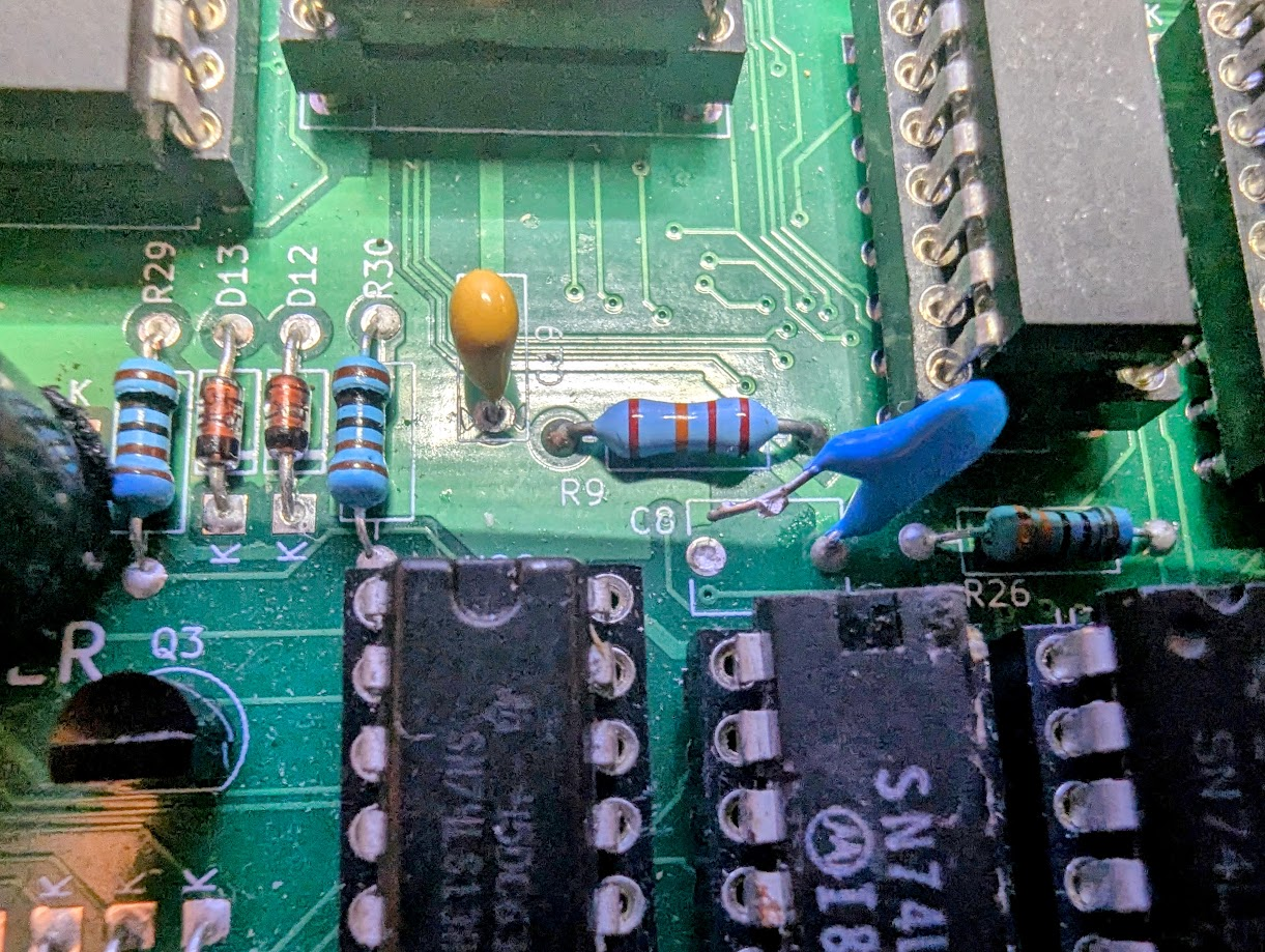
The issue did return and no amount of reseating ram chips would fix it this time. The odd character would appear on screen and no commands would work just as before. The final fix I found was to remove capacitor C8. The ace has been stable for days so hopefully thats the end of that issue.
Ongoing
So building a Jupiter Ace, was it worth it? Hell yes I’d fully recommend it. Its been a rocky road but hopefully I’ve smoothed it out a bit for anyone insane enough, I mean inspired enough. You can contact Dave for a board here.
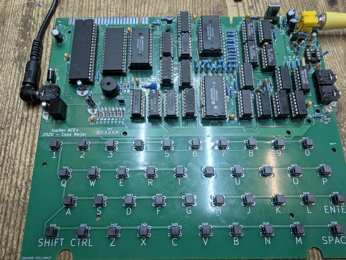
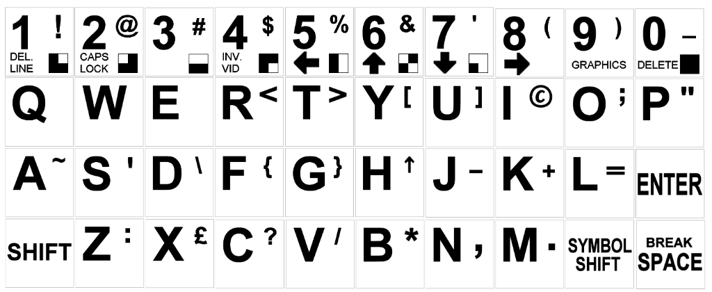
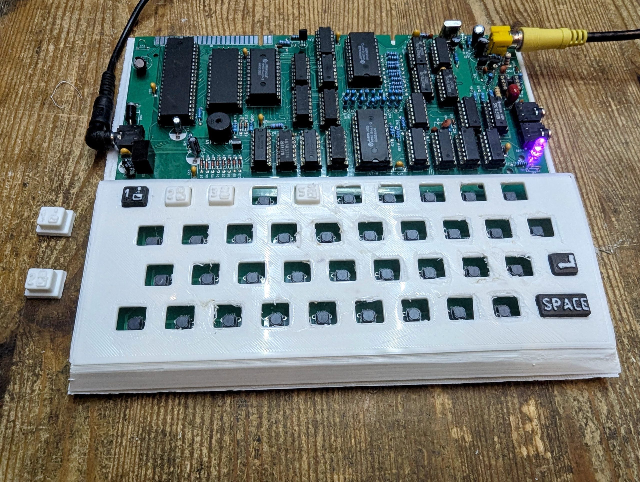
I intend to 3D print a case and some keys but first I would like to get some games loaded so will report back soon. The keys below are for reference.
Loading Games
Ok, This has been a bit problematic as with tape loading on most 8bit retro’s.
Initially I was getting no response when trying to play a WAV file from my PC to the Ace. Typing LOAD with no quotes should respond with Dict: GameName
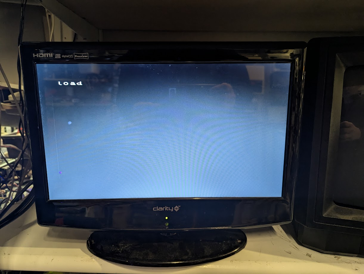
Nothing happening.
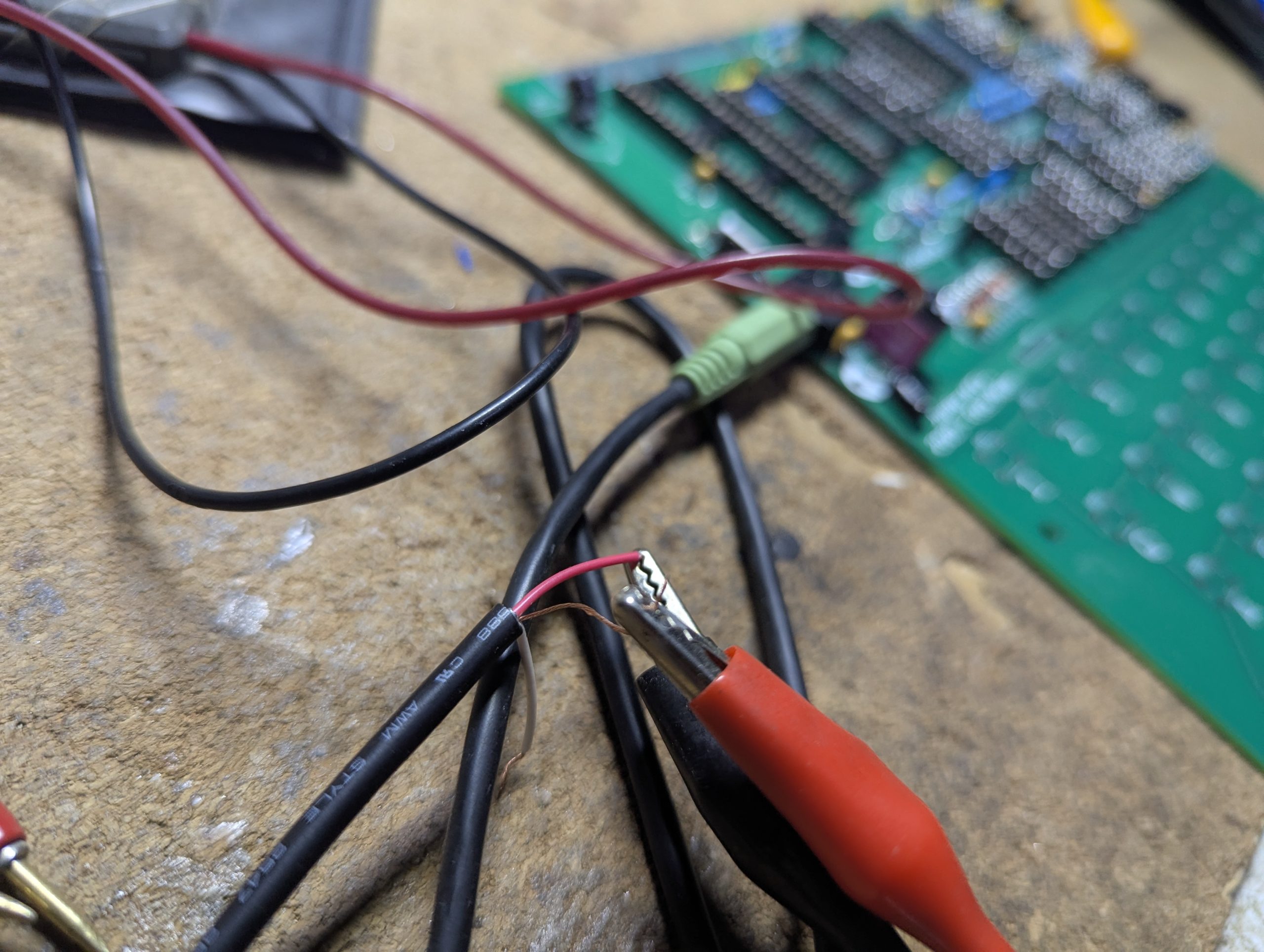
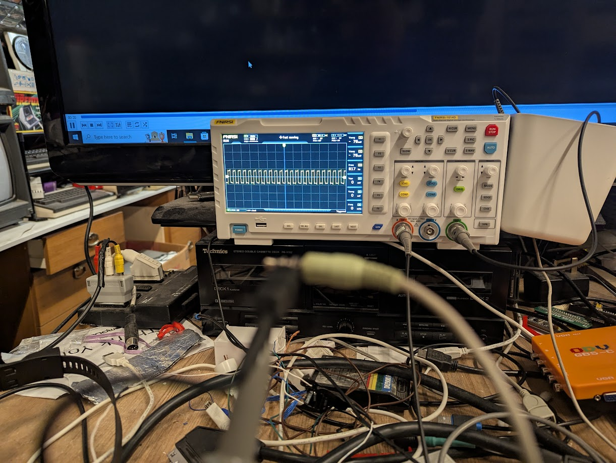
I next checked for a signal coming through the jack plug
Rabbit Holes
I went researching. Found a suggestion here which was useful as it described converting tap files to wav using the castool and this suggested that maybe my wav file was not converted properly. So I tried recreating the wav file with the castool but still no joy.
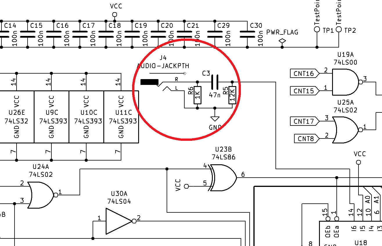
Next I found a suggestion for changing capacitor C3 from a 47nF to 470nF
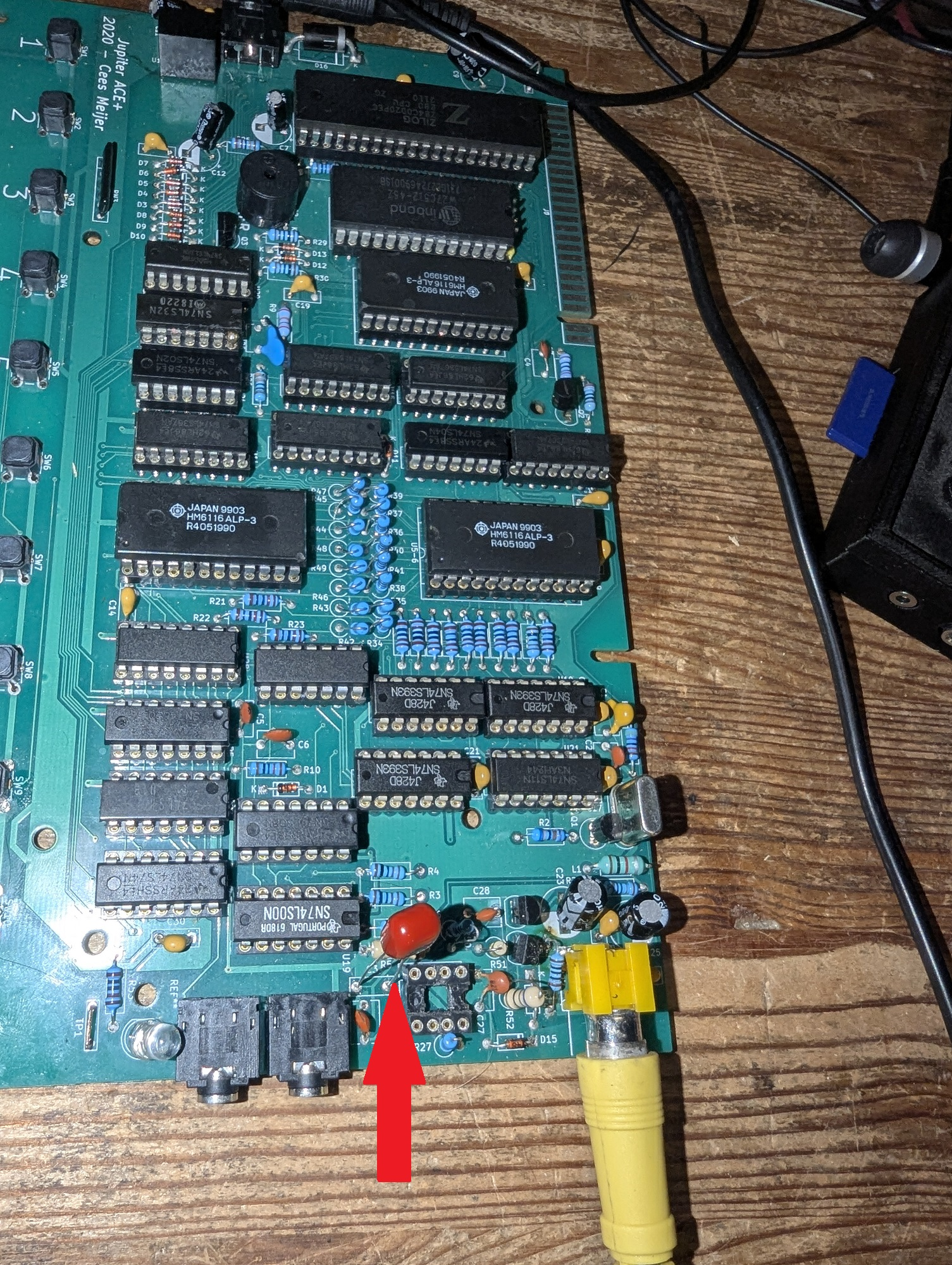
Changed but still no joy.
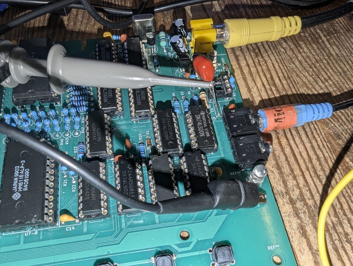
So I tried testing the signal off the new cap.
And got nothing. I thought, there should be some signal.
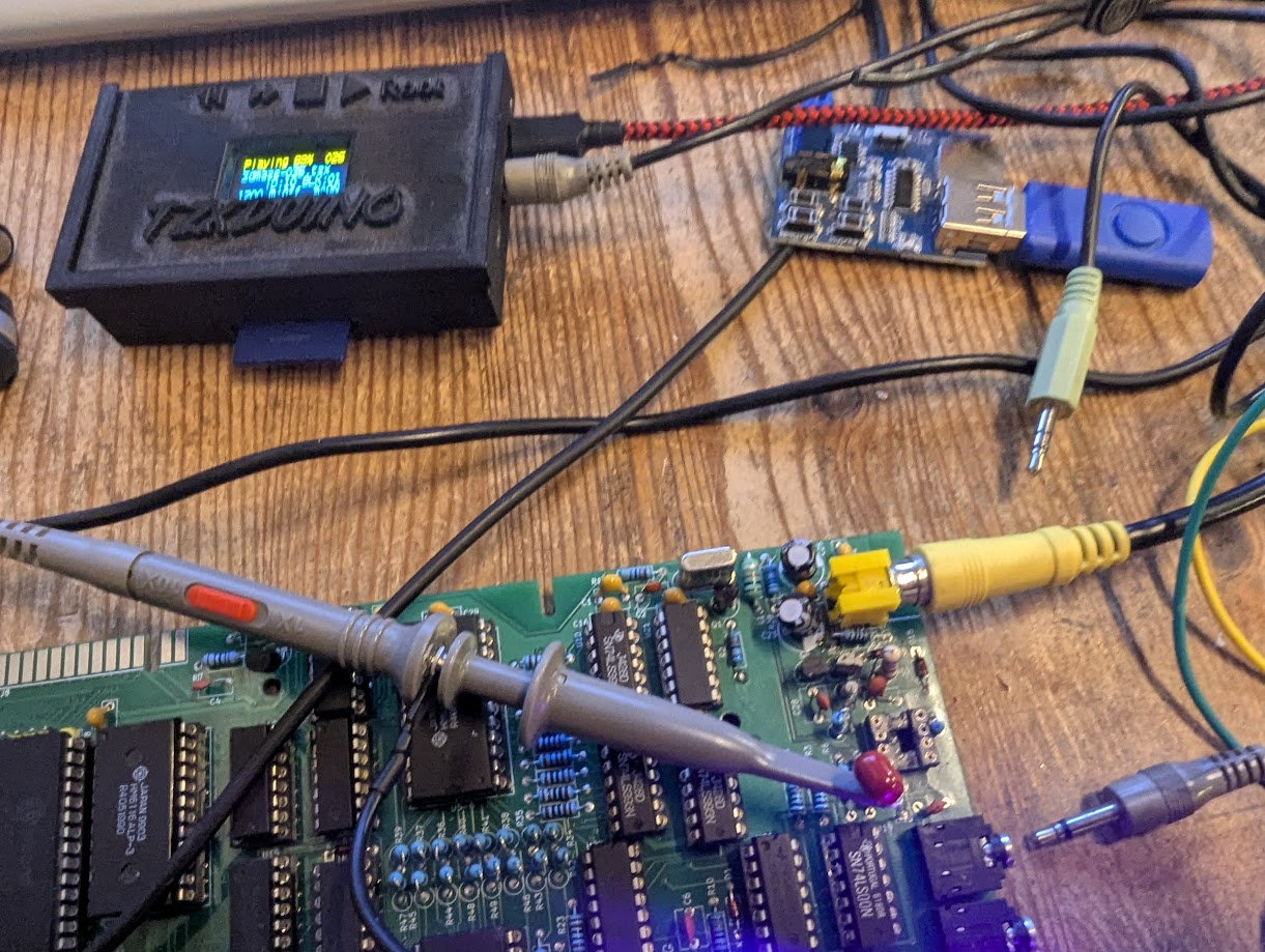
To cut long story short. I was convinced the signal coming from my PC audio was week as when testing with a Spectrum TZXDuino device I got this. Which is good enough to work on my Spectrums.
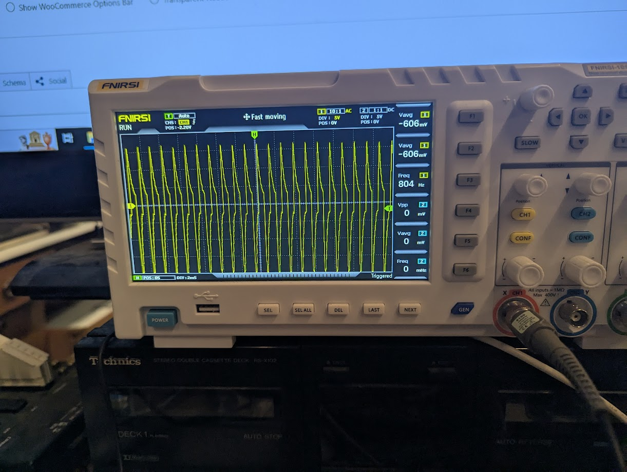
A much stronger signal but even with this still no response from the ACE.
I then tried a mono audio cable with the TZXDuino , selected a TZX file and
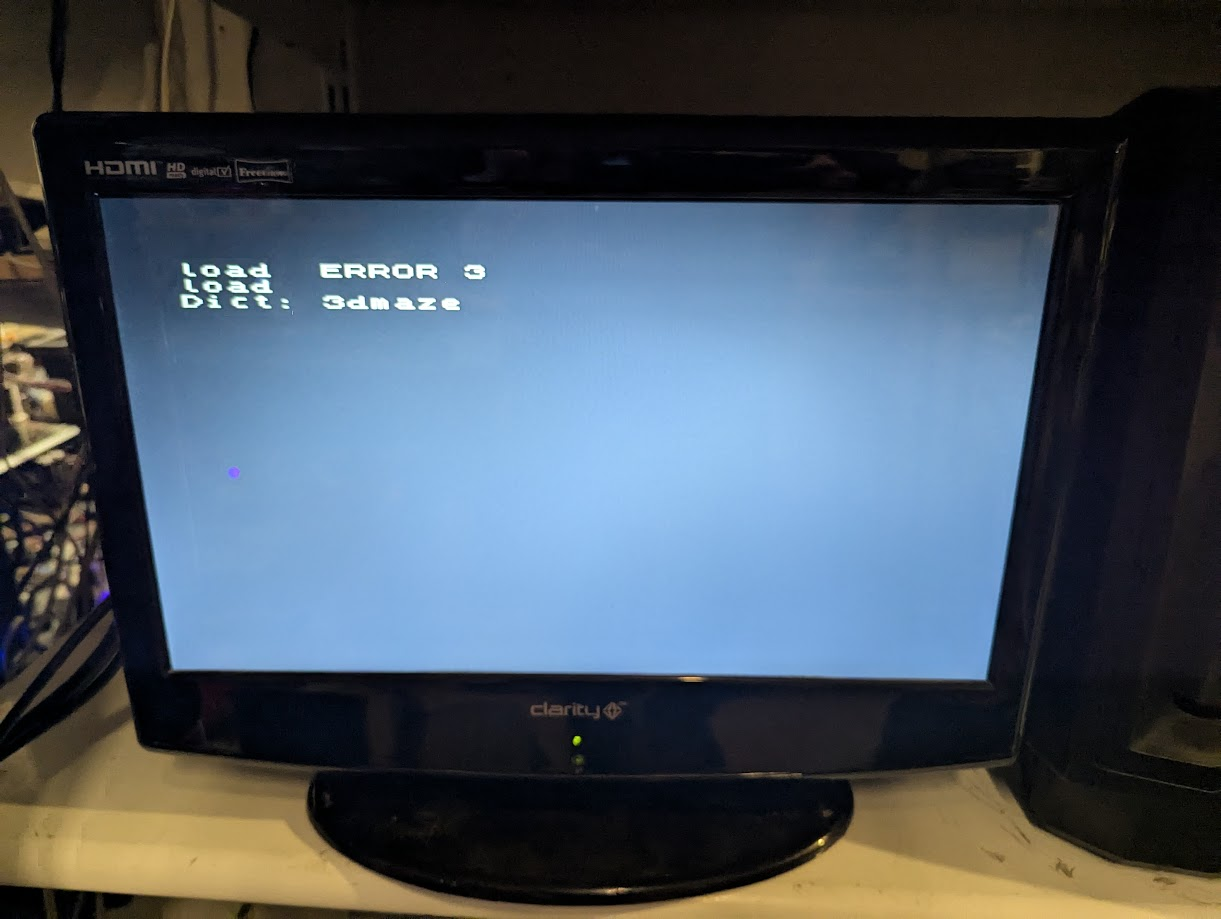
Progress, got a response. The header was being loaded with the name of the game but sadly the game would not load. I assumed it was because the TZXDuino was setup for a Spectrum which is a slightly different format to the Jupiter Ace. I needed some way of playing a wav file with a sufficiently strong signal.
After trying various devices such as a bluetooth player from mobile to a simple wav music player.
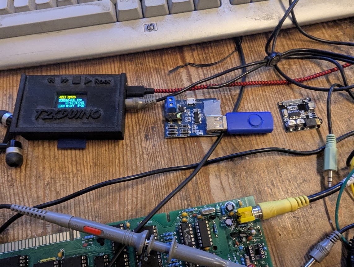
The wav music player with the USB in the center of the photo above actually provided the best signal.
Still 3D Maze wouldn’t load. I finally realised that 3Dmaze was a 19k game. The Ace is only a 16k machine. Aaaaaargh!
So I tried meteor which is 3K and finally it loaded!
Loading Games
The quirk with Ace games is that they need a manual start by typing the correct command which is normally the name of the game but this didn’t work. So was this a corrupt load?
Typing vlist reveals any commands which have been added by loading including the command to start the game itself.
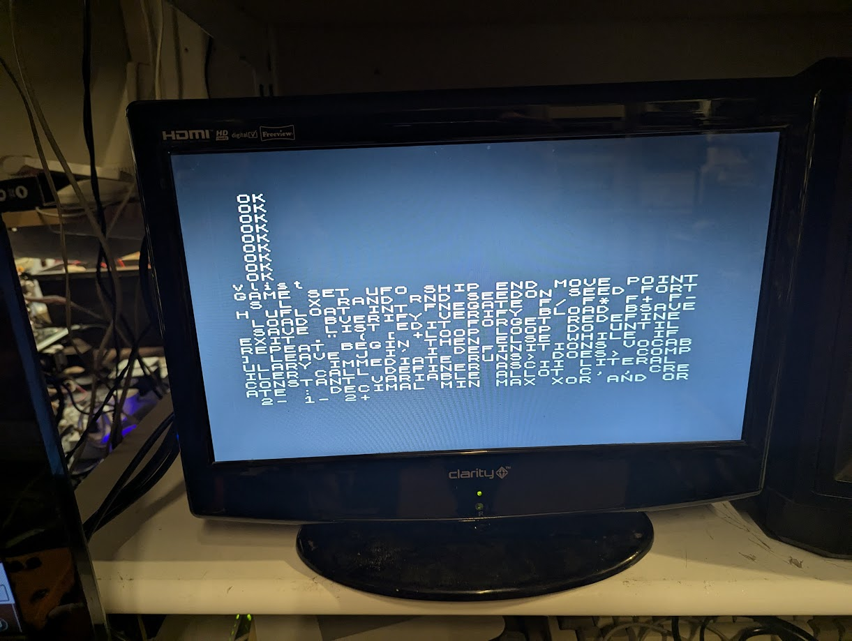
Notice the first command after vlist. “GAME”. That must be it
Success!. The game started. It was noisy, very noisy and very simple but I didn’t care, it worked!.
Loading games using the wav music player became impractical as putting a bunch of WAV’s on a USB stick and only having buttons to select next/previous track meant you wouldn’t know which WAV you were loading.
I decided to back track and try loading from PC again and for some unknown reason it worked!. I did have to remove the oscilloscope probes which were probably causing a bit of inteference or soaking a bit of signal. So why did it work this time and not before. It turned out it was the stereo jack connections. I should have realised this from the schematic. Its the left channel from the jack which is ground not the sleeve and the right channel is signal. The ground from the source (PC) jack plug needs to connect to the left channel at the Jupiter Ace end and the right channel from the PC connects to the right channel on the Jupiter Ace. I must have had this connected differently before.
Notice the R and L on the jack plug lines. L goes to ground.
This is how I’ve wired my PC to Jupiter Ace audio cable.
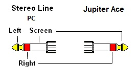
NB This wiring configuration only works on PC and not TZXDuino
TZXDuino to Jupiter Ace Wiring as follows
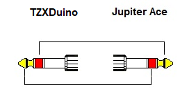
Even though the TZXDuino does not natively support the Jupiter Ace I found some code here to convert Jupiter Ace Tap files to TZX which work with the TZXDuino. So the Ace is finally, reliably, loading games. Happy days.
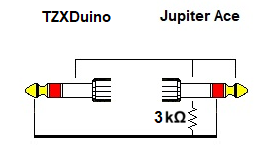
It turns out the games wouldn’t load unless I had my oscilloscope connected to ground. I assume this was bias’ing the signal. A small modification with a 3k resistor and the connections now need to be as follows for TZXDuino loading.
Final Thoughts
I need to make a case and a set of keys and 16k is not enough so I’m going to have a go at creating a ram expansion so I can play all the games. Watch this space.
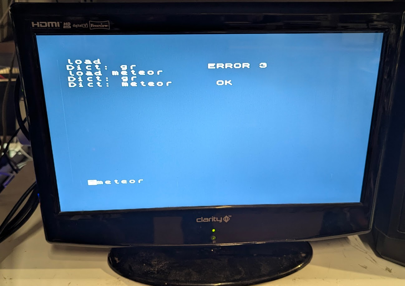
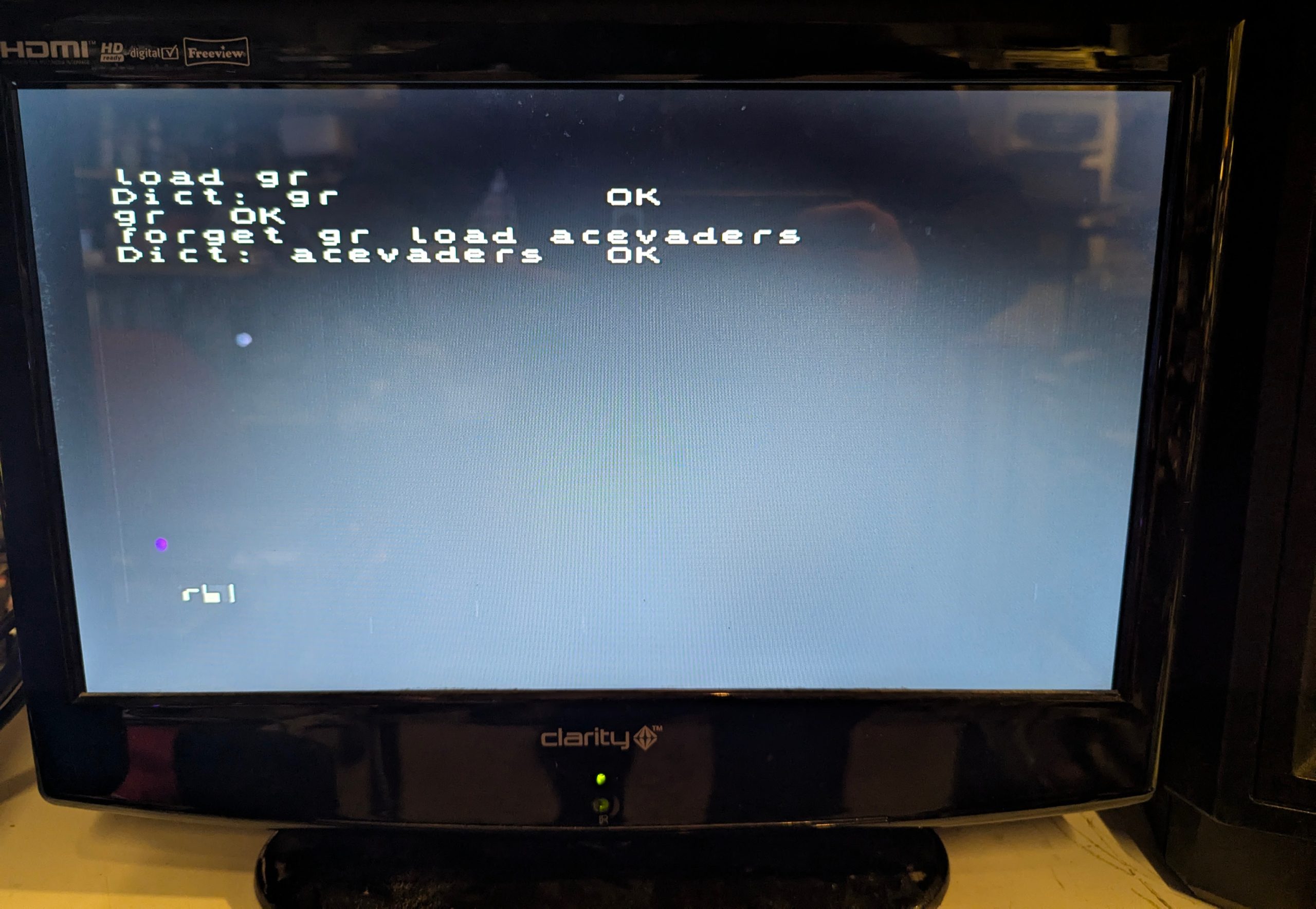
BTW I discovered I was loading games without the graphics which is a two part load. So if loading first displays a ‘Dict: gr‘ then this is the graphics part so do as follows e.g acevaders
load gr
Once Loaded pause the TZXDuino
gr
forget gr
load acevaders
Unpause TZXDuino
r
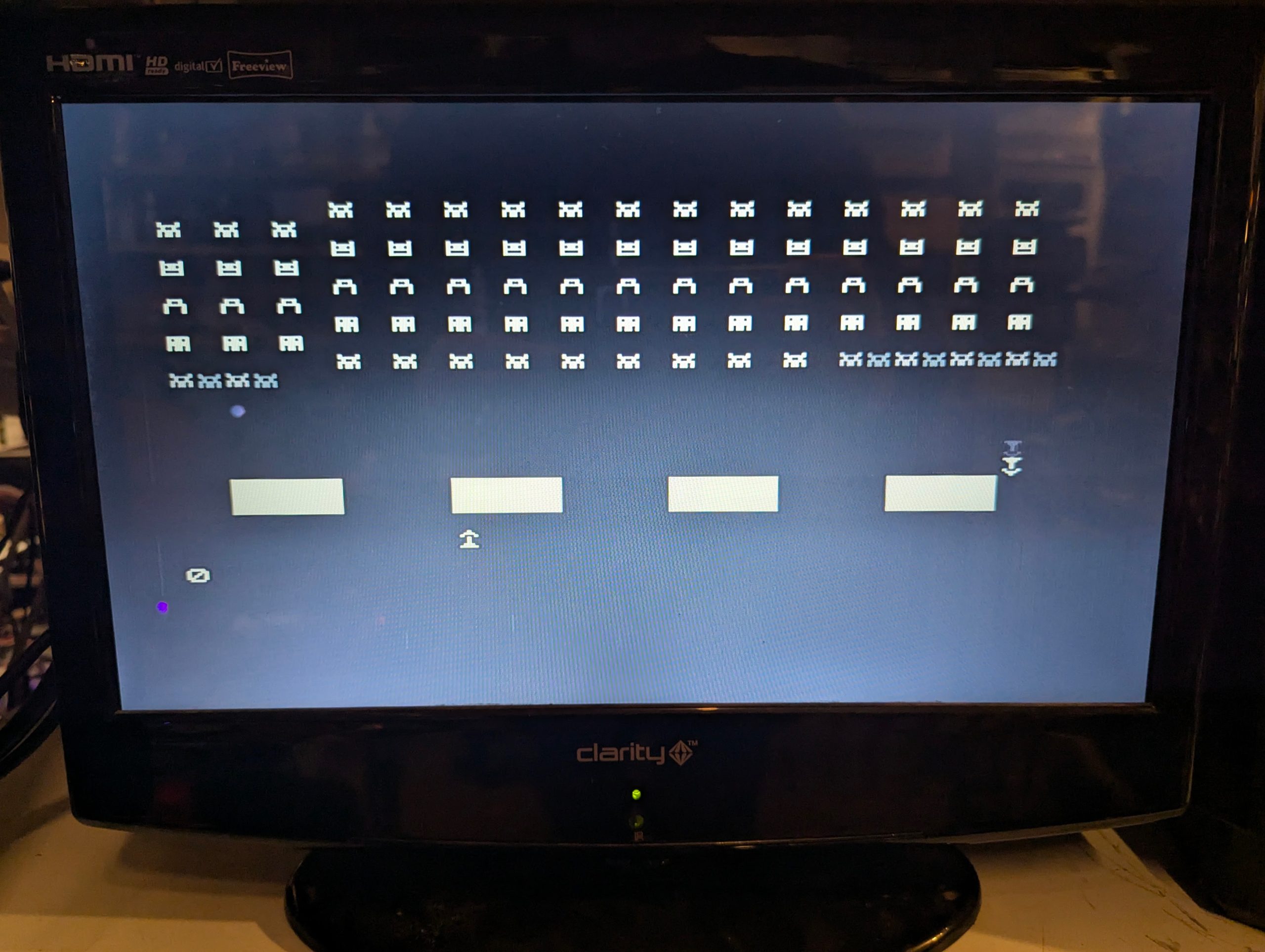
And this is how the game Meteor looks with graphics loaded
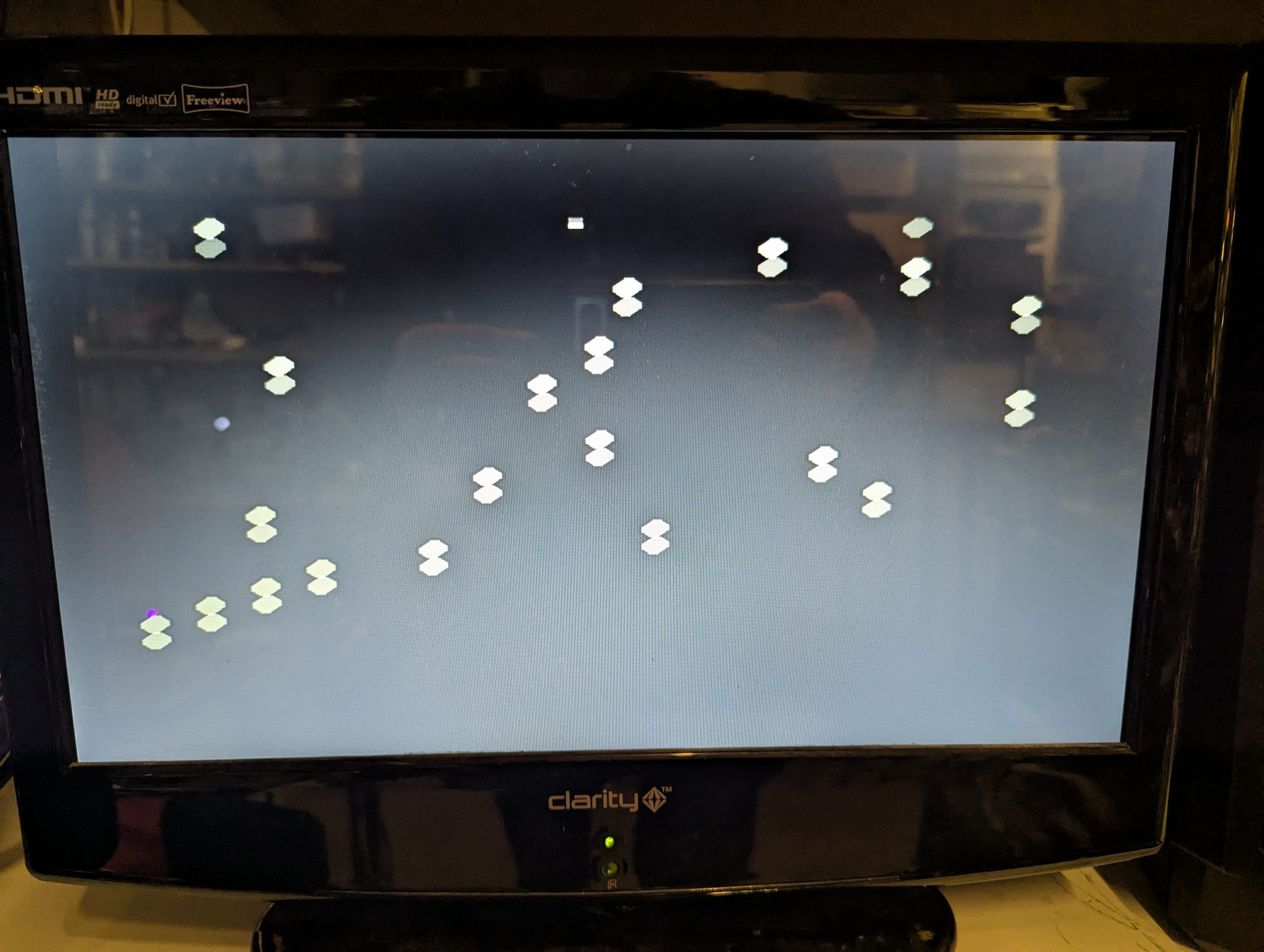
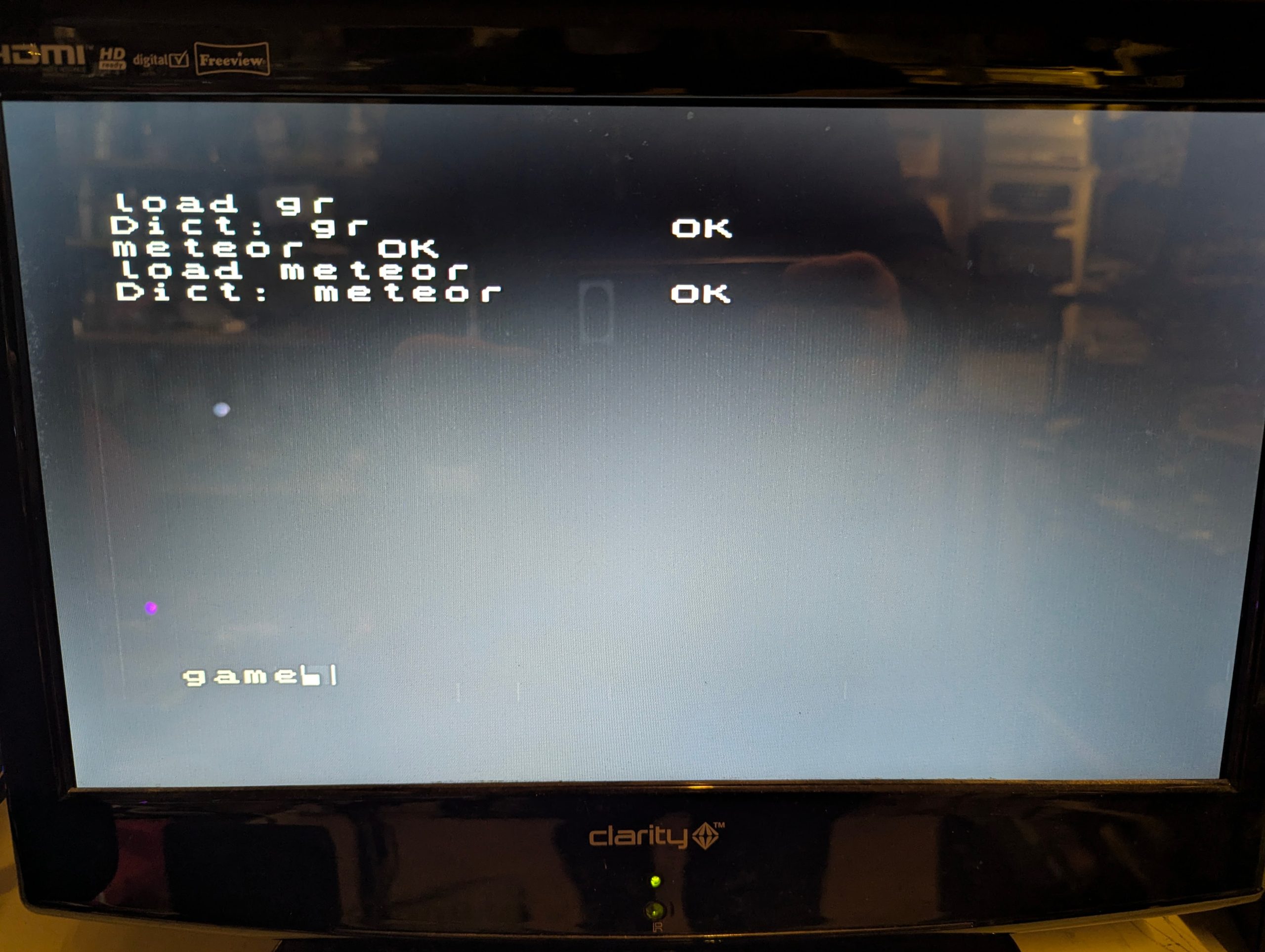
Note the loading of this game required ‘meteor’ to be typed after loading gr and ‘game’ to start the game. Use vlist to show the required command after loading.
Case and Keys
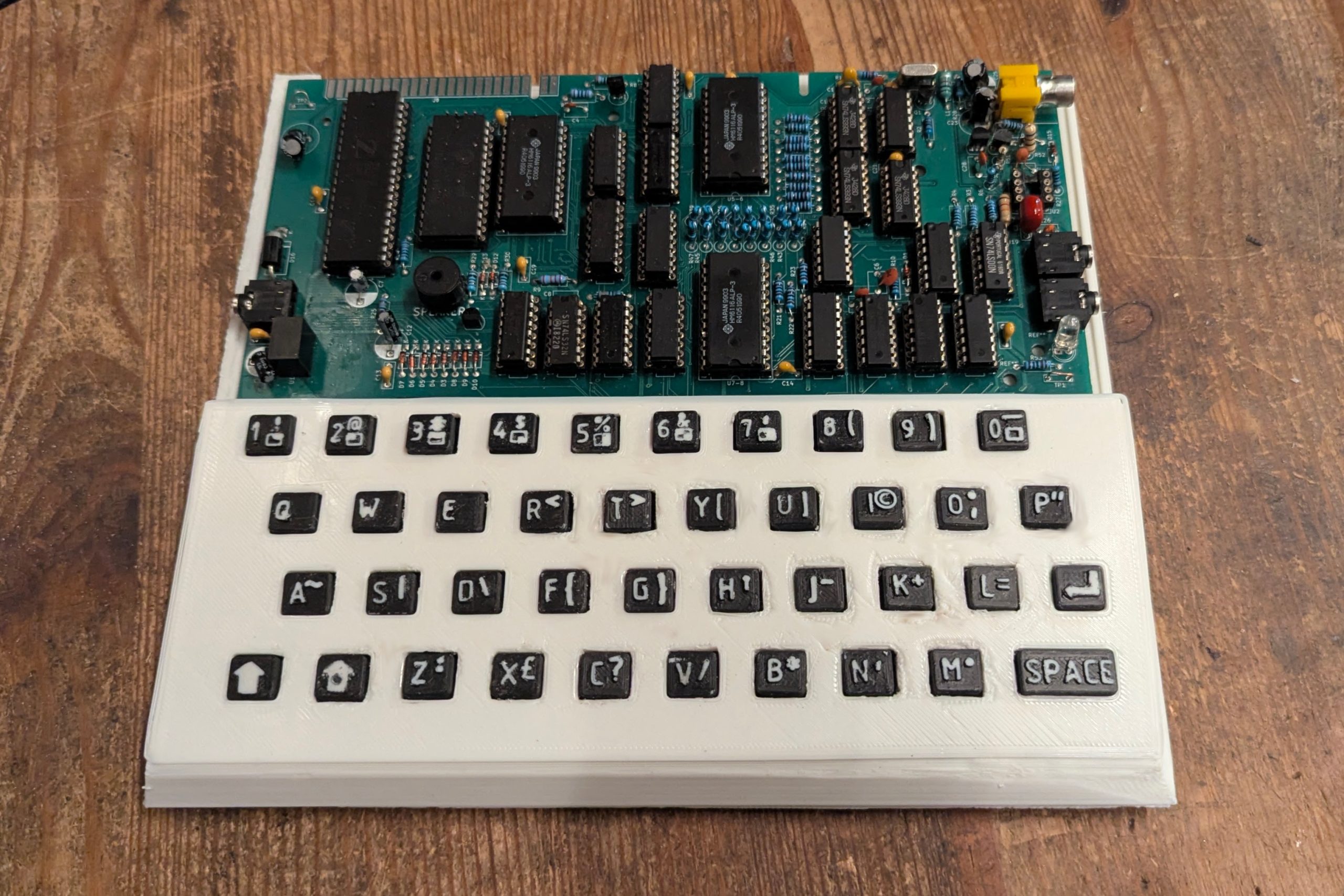
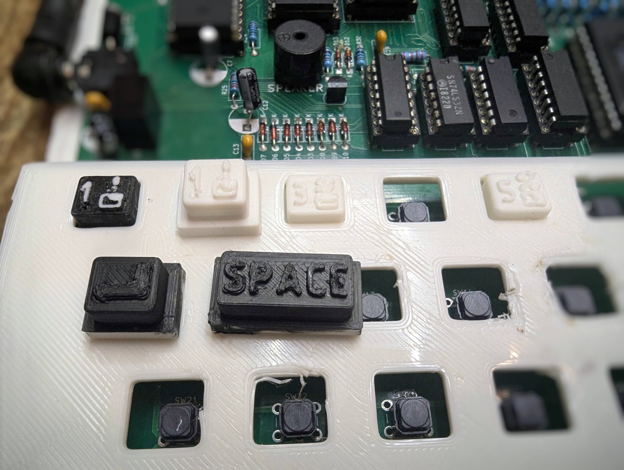
I’ve rough printed the base and keyboard cover due to the very long time for the print , a full day!, and also because I wasn’t sure how the motherboard would fit. Its a bit rough but its fine for now. I’m detail printing the keys as they only take about 10 minutes each and also because the symbols need the detailed resolution. I’ve experimented with the best look for the keys which is printing in white , painting the key black and sanding the top of the key to reveal the letter and symbol in white.
The keys are in various states of finish here.
Keyboard Assemble
With all the keys printed painted and sanded here is the final result.