
I acquired this from FBM for a very reasonable price. It was the perfect nostalgic piece for me as I used to work with these Amstrad PC’s back in the 80’s. During my Information Technology degree at Sheffield University I was on a industrial placement year for Hepworth Refractories in Worksop. This was a massive manufacturing company in the UK and my site spanned a 60 acre manufacturing complex. When I arrived they had two of these PC’s and that was it!. Paperwork was flowing everywhere between departments and the odd letter was printed and sent via snail mail to suppliers and customers. The potential for upgrading this site with new technology was limited only by my imagination and so my career began. The Amstrads were soon replaced but not before creating various stock control, machine monitoring and production planning software. This was a dream placement for me as I wasn’t sure what I wanted to do for a career but knew it would be something to do with computing. At the end of my placement I was given a nice bonus and a job offer. I finished my degree but couldn’t wait to get back to Work. I stayed with Hepworths for seven years finally leaving behind multiple LAN networks, full plant monitoring and control systems and countless other business management systems. What fun!.
Thats enough babbling on.
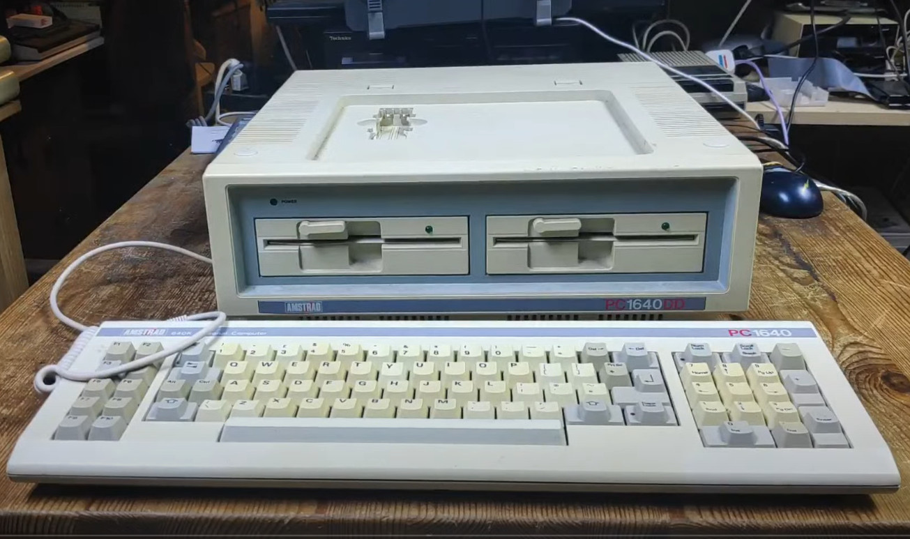
So back to this Amstrad. Sadly it is missing a monitor which means its dead. The monitor was the power source for the base unit so I first had to figure a how to power it up. The back of the unit has the following ports.
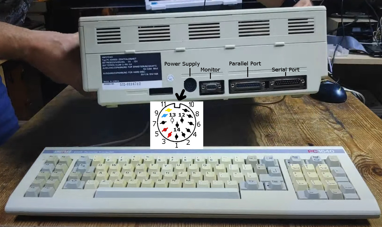
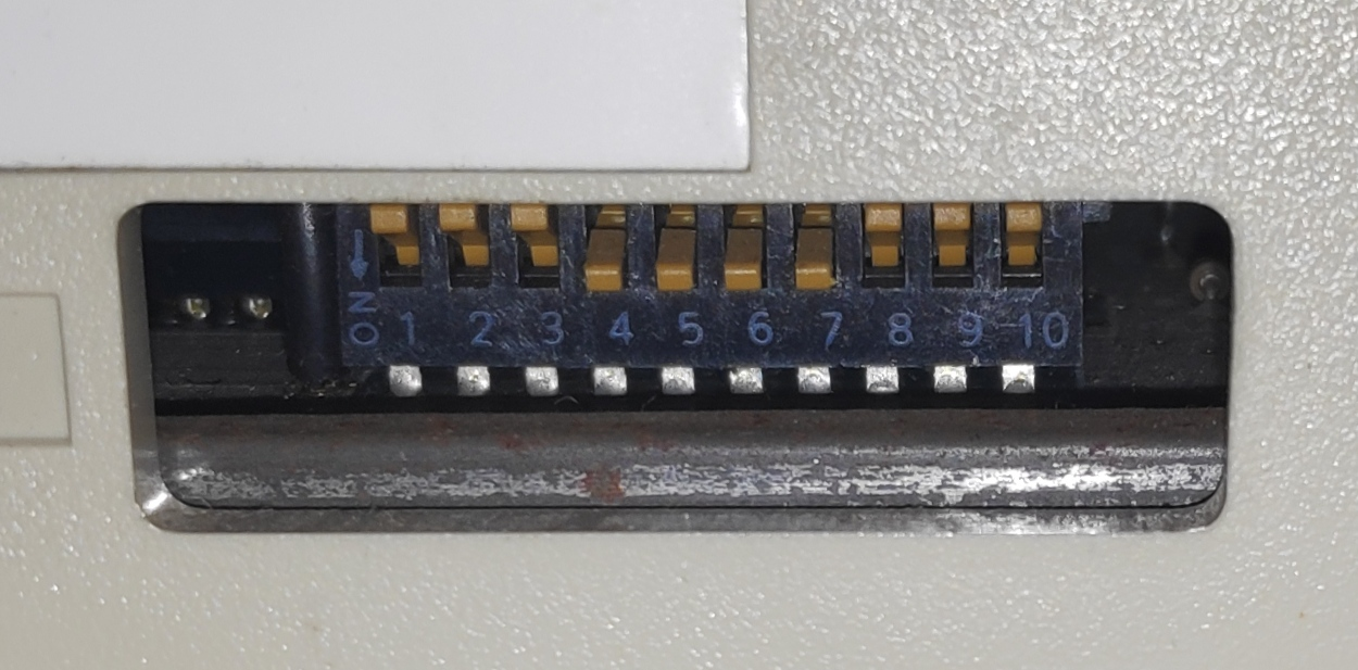
The little window on the bottom left of the ports has a number of dip switches for selecting various video modes.
The power supply port is a 14 pin din socket and the pins are described INCORRECTLY!! in the technical manual . This technical manual shows the PSU pinout but this is not viewed as looking at the rear of the computer but looking at the front of the plug. The other ports in the technical manual are viewed as looking at the rear of the computer. It was important to double check where the voltages and grounds need to connect so I did a continuity test on the top right pin of the socket to the outer shell (ground) of the other ports e.g. monitor or serial etc. This confirmed that the ground pins were on the right of the socket and therefore the voltages were on the left. Get this wrong and bang!.
| Pin | Assignment | |
|---|---|---|
| 1 | Not Connected | 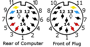 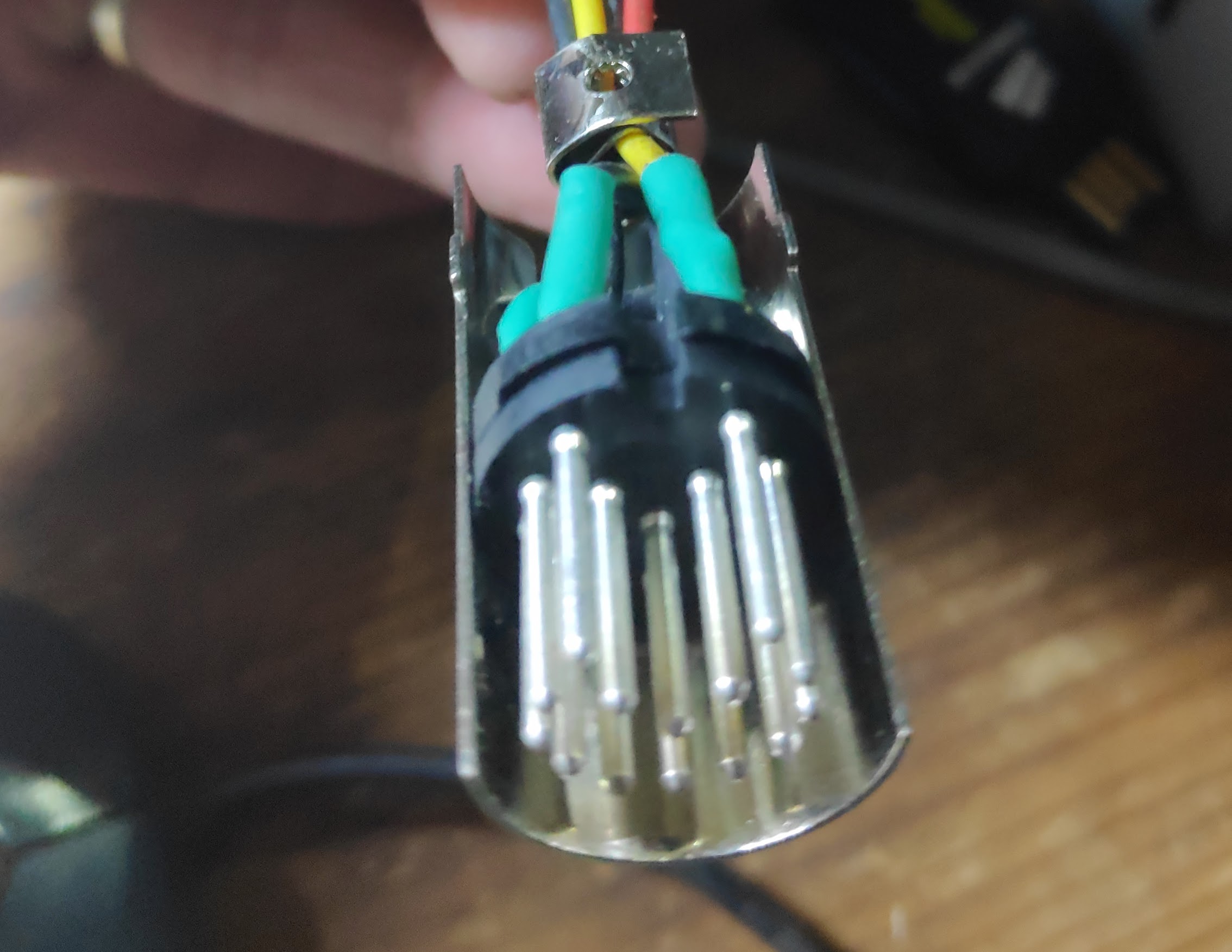 Power Connector |
| 2 | 0 Volts DC Black | |
| 3 | + 5 Volts DC Red | |
| 4 | 0 Volts DC Black | |
| 5 | + 5 Volts DC Red | |
| 6 | Not Connected | |
| 7 | Not Connected | |
| 8 | 0 Volts DC Black | |
| 9 | – 12 Volts DC Blue | |
| 10 | 0 Volts DC Black | |
| 11 | + 12 Volts DC Yellow | |
| 12 | 0 Volts DC Black | |
| 13 | – 5 Volts DCWhite | |
| 14 | Not Connected |
For powering the computer and floppy drives it is only necessary to connect 12v, 5v and ground. The negative voltages are redundant unless connecting certain ISA cards or using the serial port. I therefore just connected the Red 5v wires to pins 3,5 , the Yellow 12v wire to pin 11, and a couple of black ground wires to pin 1,2.
Substitute Monitor
The monitor connector has a 9 pin D female socket. Its pinout is as follows:
| Pin | Assignment | |
|---|---|---|
| 1 | Ground | ![[Monitor pinout]](https://www.seasip.info/AmstradXT/1640tech/video.png) Video Connector Video Connector |
| 2 | Secondary Red (r) or Ground (GND) | |
| 3 | Primary Red (R) | |
| 4 | Primary Green (G) | |
| 5 | Primary Blue (B) | |
| 6 | Secondary Green (g) or Intensity (I) | |
| 7 | Secondary Blue (b) or Mono Video (V) | |
| 8 | Horizontal SYNC | |
| 9 | Vertical SYNC |
The same pinout is used for all three Amstrad PC display types but the interpretation of a particular pin’s function varies with the connected device. In addition certain devices require that pin 2 exhibit a full ground characteristic and this is accomplished by switch 8 (sw8) at the rear of the PC1640. When sw8 is in the OFF position pin2 is grounded. When sw8 is in the ON position then the secondary red (r) signal is routed through to pin 2 (See section 1.22 – PC1640 Switch Settings.)
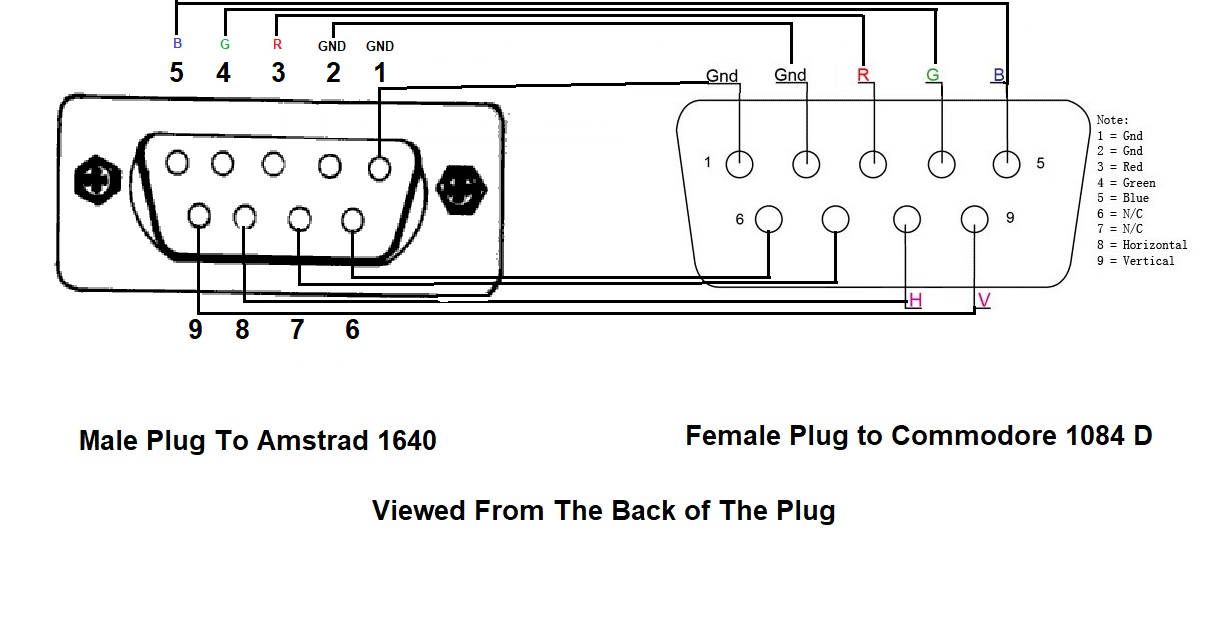
Commodore 1084 D 9 pin male Input matches the signals from the Amstrad.
I created a simple one to one cable from Amstrad 1640 to Commodore 1084 D
Moment of truth
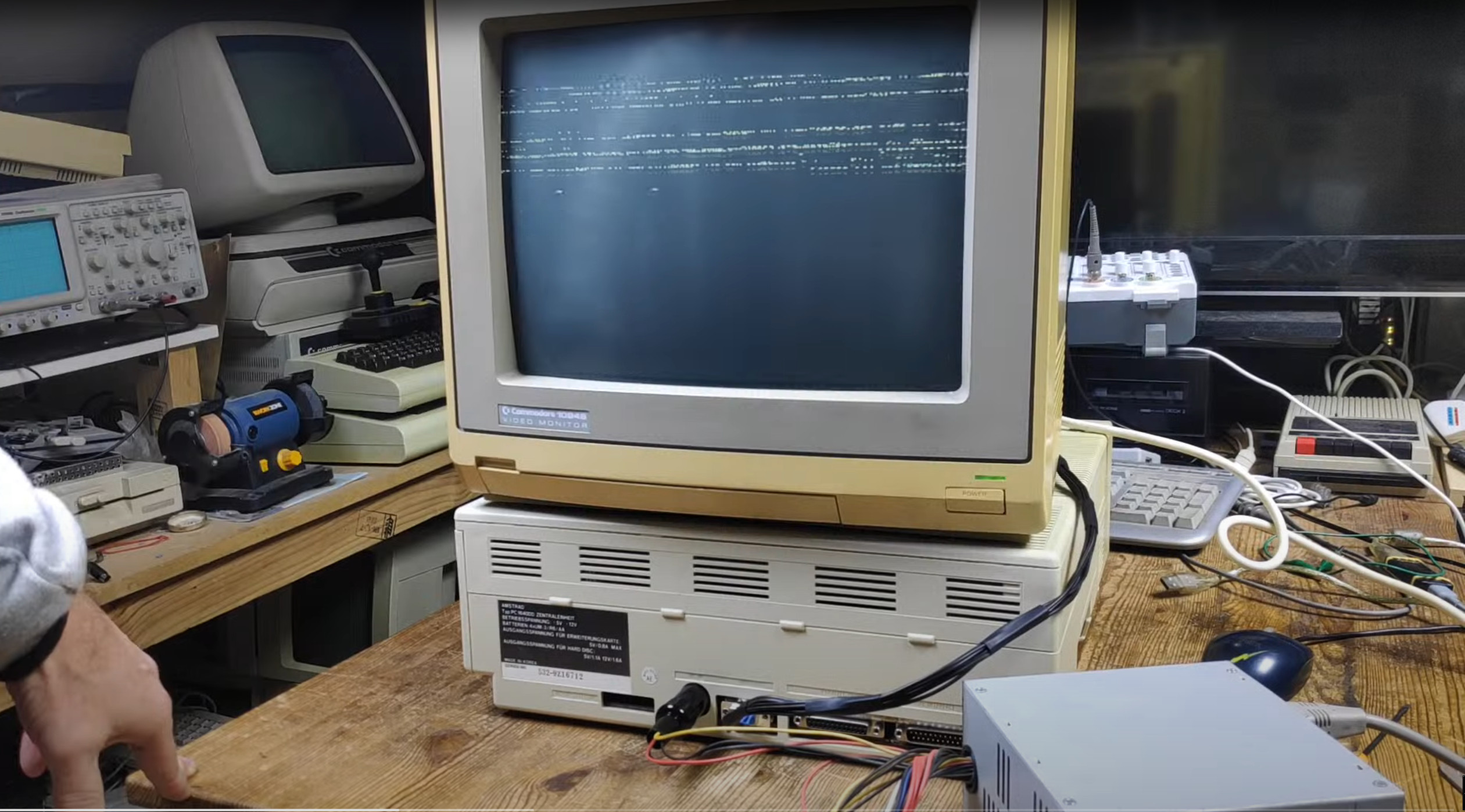
I get scrolling corrupt lines. Now I’m worried that the 1084S isn’t upto the job of receiving ega signals.
A bit of tinkering with the dipswitches on the Amstrad and…
Thats a relief!. Its 40 column mode but at least it displays on the Commodore 1084S and I now know its working. Woohoo!
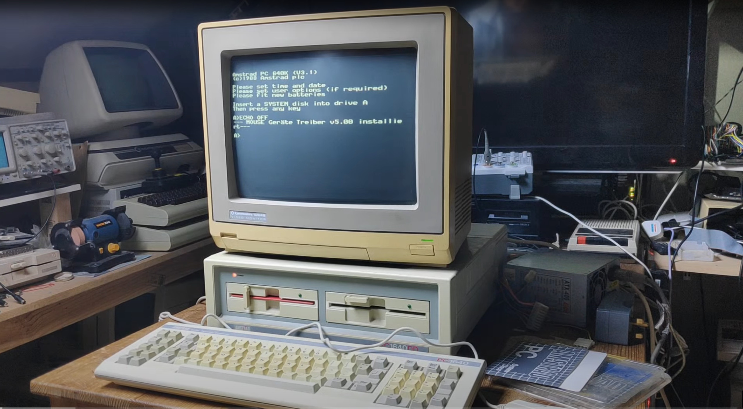
A bit more tinkering and….
Yes! 80 column mode. Next question is it in colour or black and white and whats with the German?
To answer to colour question I managed to run GEM and run the doodle app.
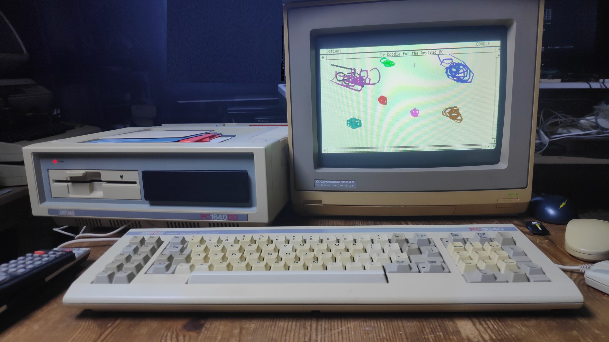
Doodle works and in colour!. What a masterpiece. Sadly I forgot to save it.
The dispswitches are set as follows which give 80 columns with EGA in colour. I tried the EGA with 350 lines but this is with 40 columns.
| SW1 | SW2 | SW3 | SW4 | SW5 | Hardware mode |
|---|---|---|---|---|---|
| Off | Off | On | Off | Off | EGA with mono monitor (DISPLAY MDMONO) |
| On | On | On | Off | Off | EGA with EGA monitor, 200 lines (DISPLAY ECD200) |
| Off | On | On | Off | Off | EGA with EGA monitor, 350 lines 40cols (DISPLAY ECD350) |
| Off | Off | Off | On | On | EGA with CGA monitor, 80 column (DISPLAY CDCOLOR) * |
| On | Off | Off | On | Off | EGA with CGA monitor, 40 column |
| Off | On | Off | On | Off | Secondary EGA, mono monitor |
| Off | Off | On | On | Off | Secondary EGA, EGA monitor, 350 lines |
| On | Off | On | On | Off | Secondary EGA, EGA monitor, 200 lines |
| Off | On | On | On | Off | Secondary EGA, CGA monitor |
| Off | Off | On | Off | On | MDA (DISPLAY MDTEXT) |
| Off | Off | Off | On | On | CGA 80 column (DISPLAY CDMONO) |
| On | Off | Off | On | On | CGA 40 column |
| Any | On | Off | On | On | Secondary MDA |
| Any | On | On | On | On | Secondary CGA |
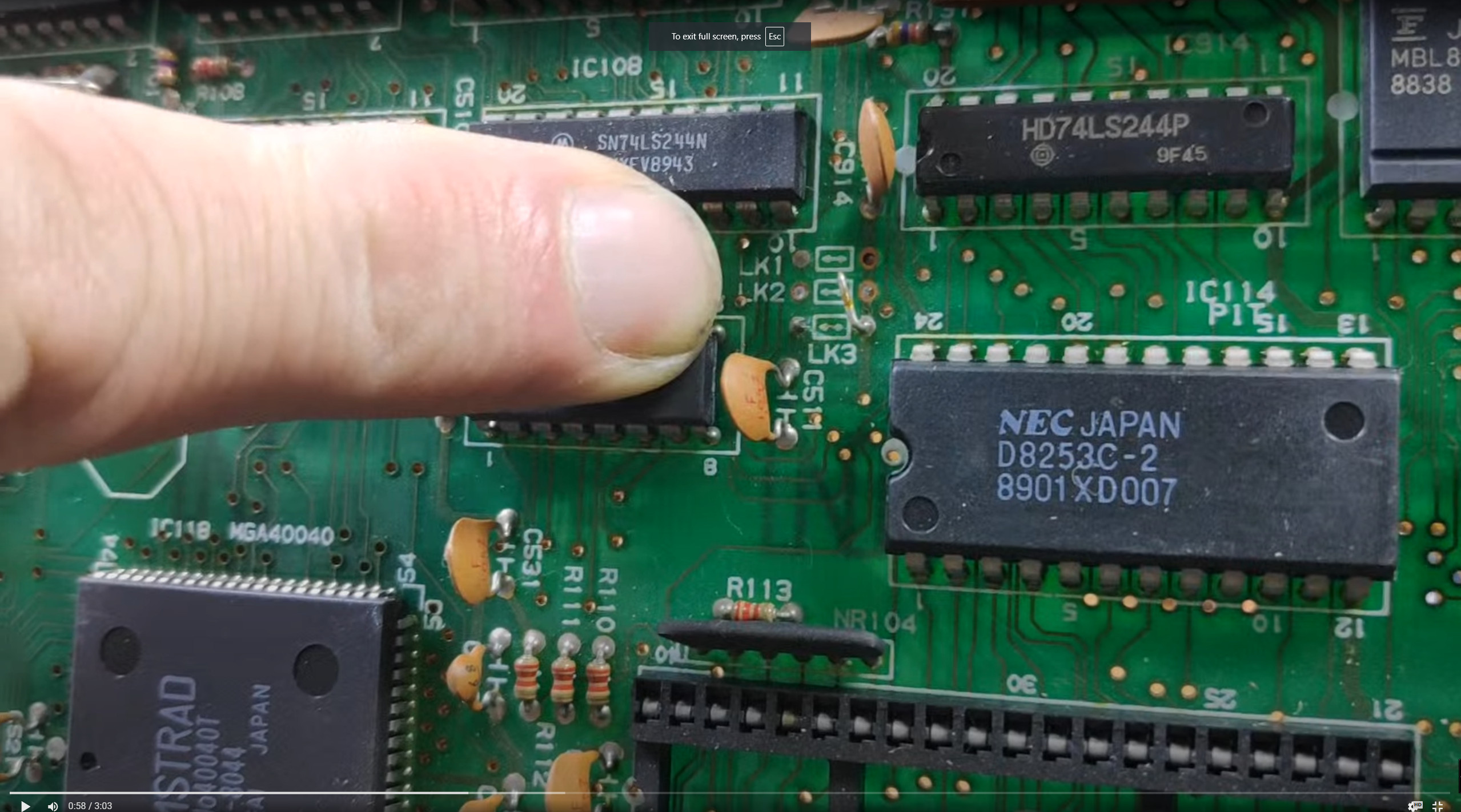
Initially I thought the German messages were due to the links on the mother board specifically LK1 – LK3 see technical manual.
| LK1 | LK2 | LK3 | ROS Language |
|---|---|---|---|
| OFF | OFF | OFF | English. |
| OFF | OFF | ON | German. |
| OFF | ON | OFF | French. |
| OFF | ON | ON | Spanish. |
| ON | OFF | OFF | Danish. |
| ON | OFF | ON | Swedish. |
| ON | ON | OFF | Italian. |
| ON | ON | ON | Diagnostic Mode. (English) |
This was however a wild, time consuming, goosechase resulting in complete disassembly of the machine. At least it gave me a chance to give it a good clean.
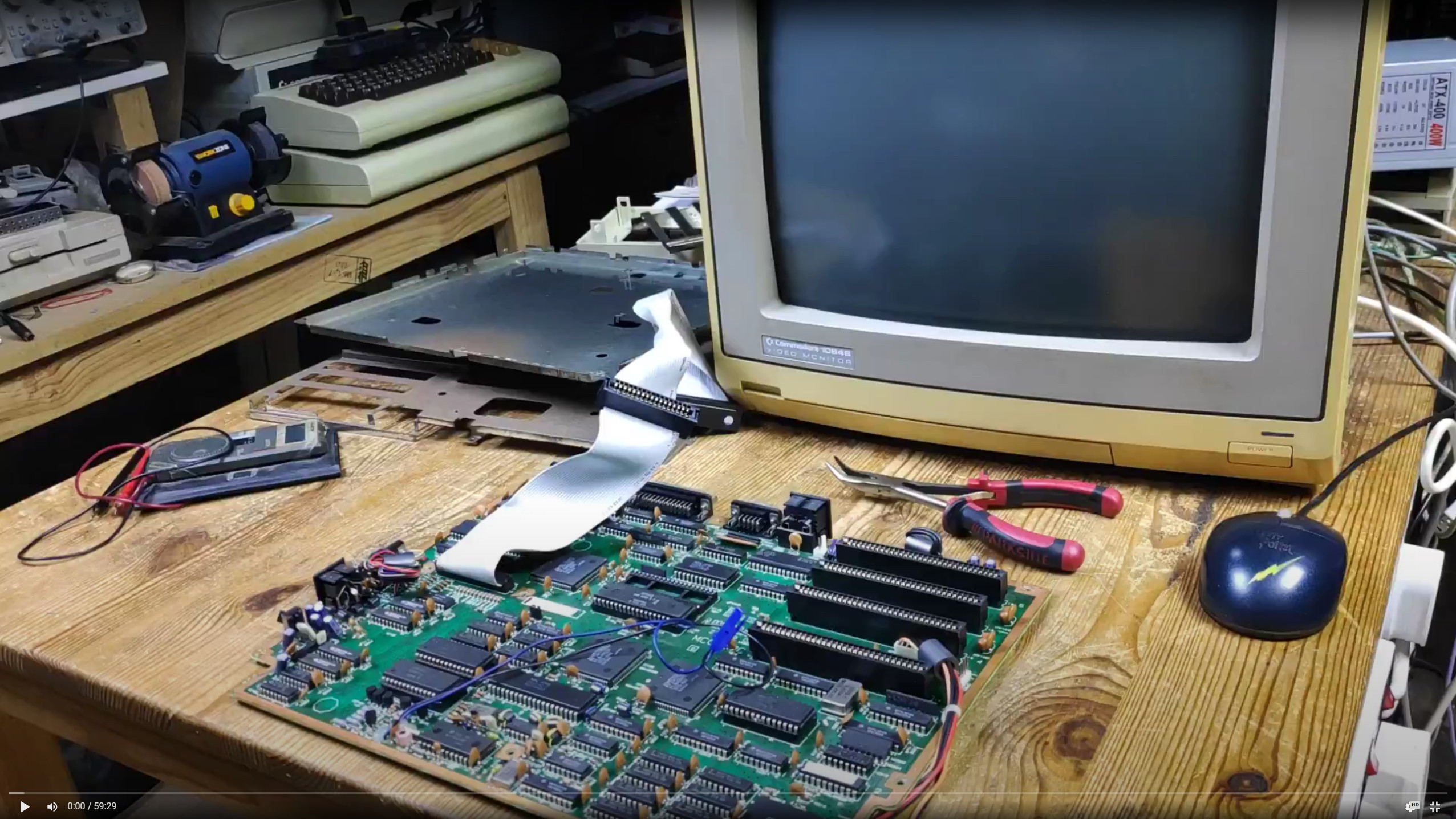
I eventually found the links on the motherboard and they were all off i.e set to English although it looks like it was originally German.
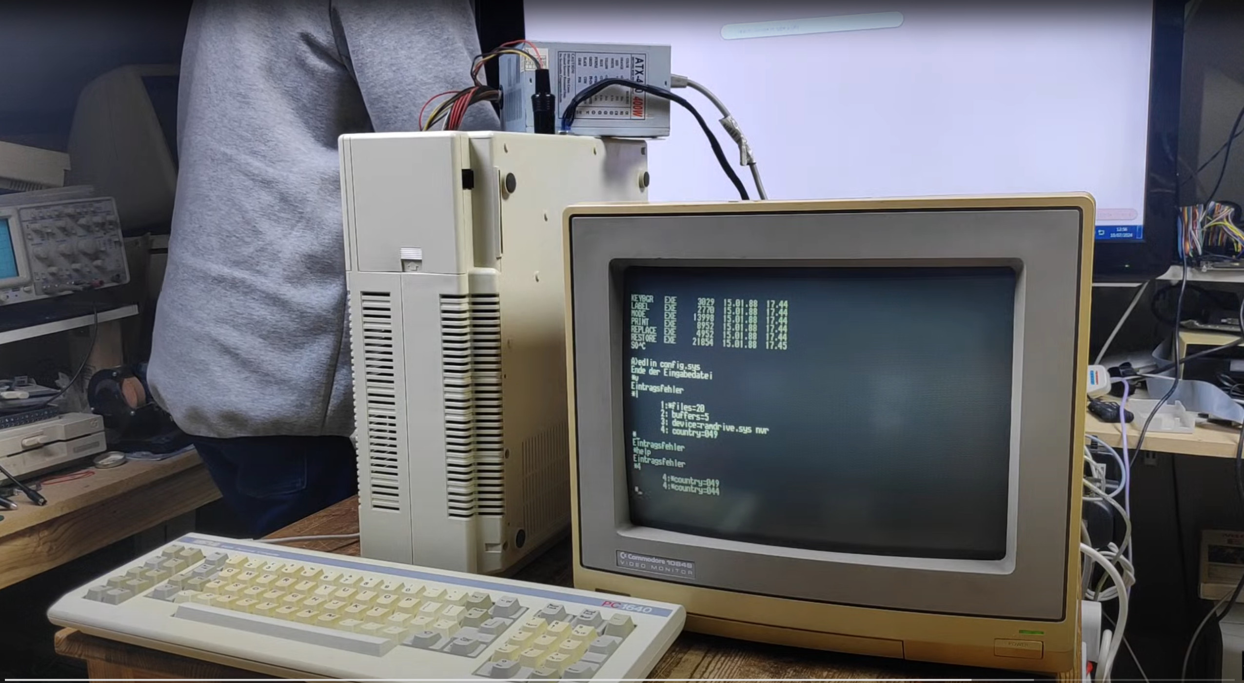
So what was going on?. I was very rusty using DOS again but remembered the config.sys and autoexec.bat files were used to set language and country etc.
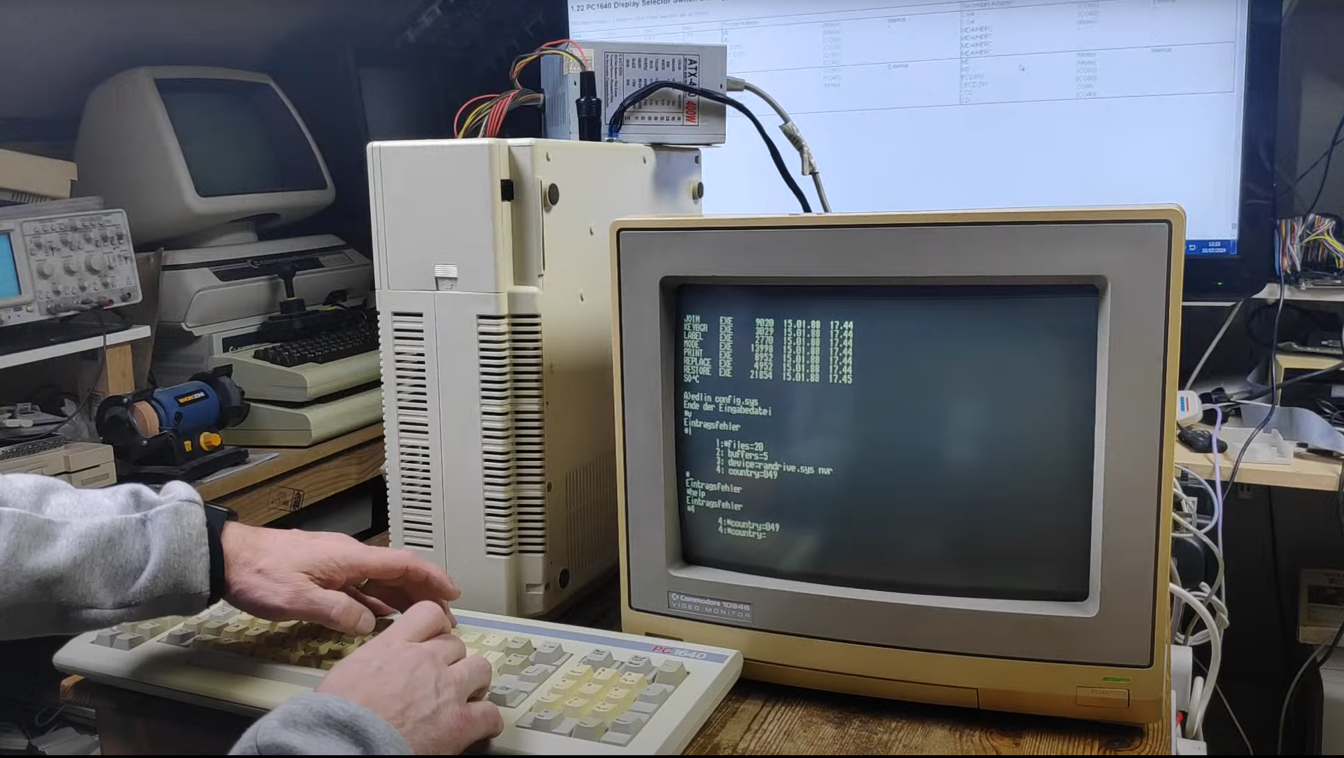
Does anyone remember how to use edlin because I don’t.
Anywho setting the language and country in the config.sys and autoexec.bat made no difference.
Then I looked closer at the disk labels. Arse!
The answer was here
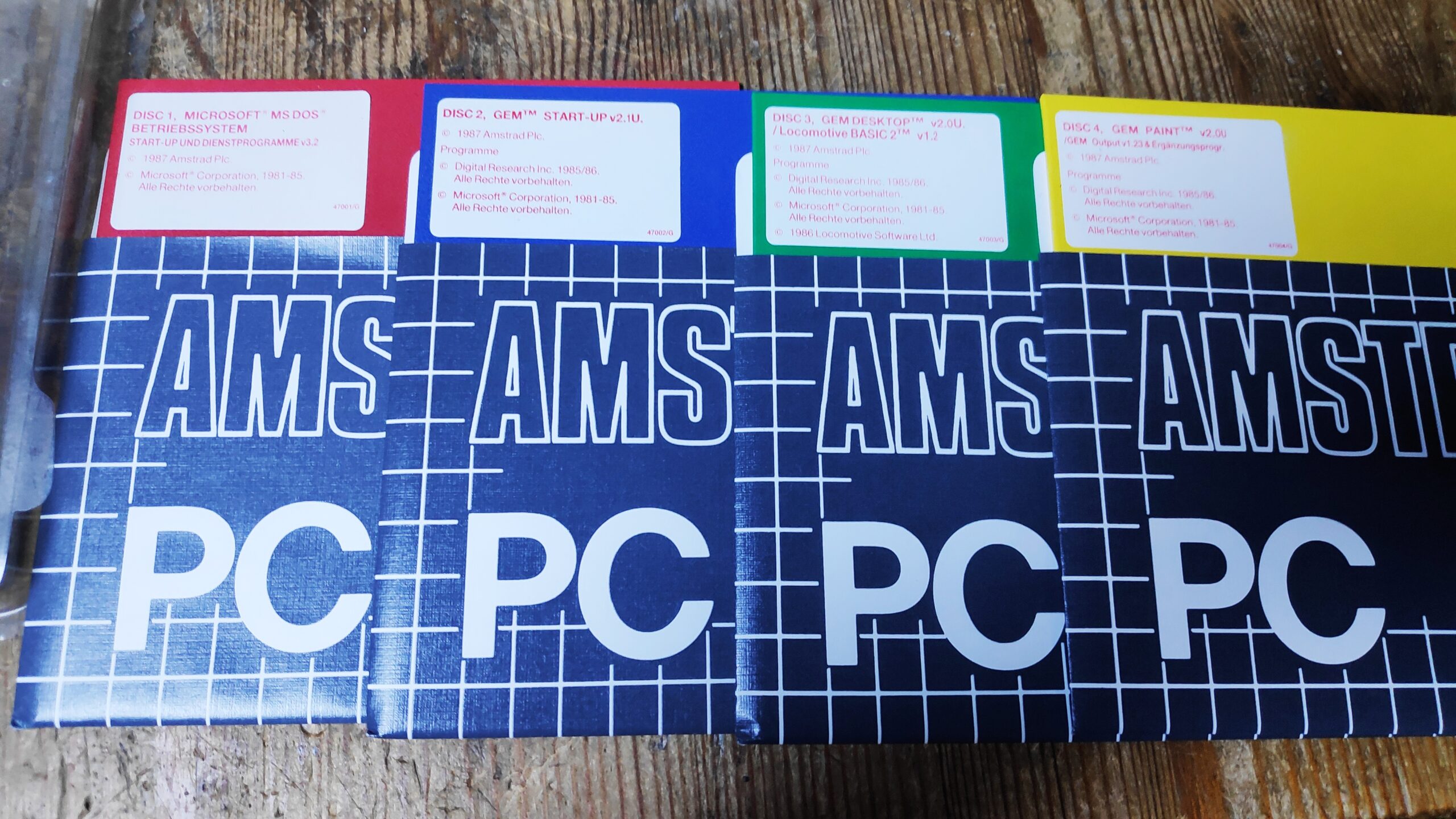
Did you spot it. Look closer.
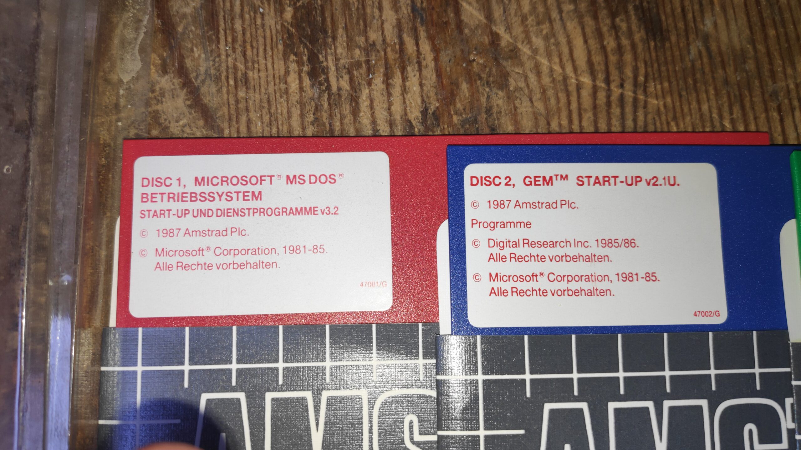
Simples this is a set of german disks. I just assumed the disk contents were standard across countries but sadly I was mistaken. It seems this particular Amstrad is well travelled and came with the original disks from its original point of origin, Germany. Motherboard link LK3 was originally set enabled and when it was brought to England was disconnected.
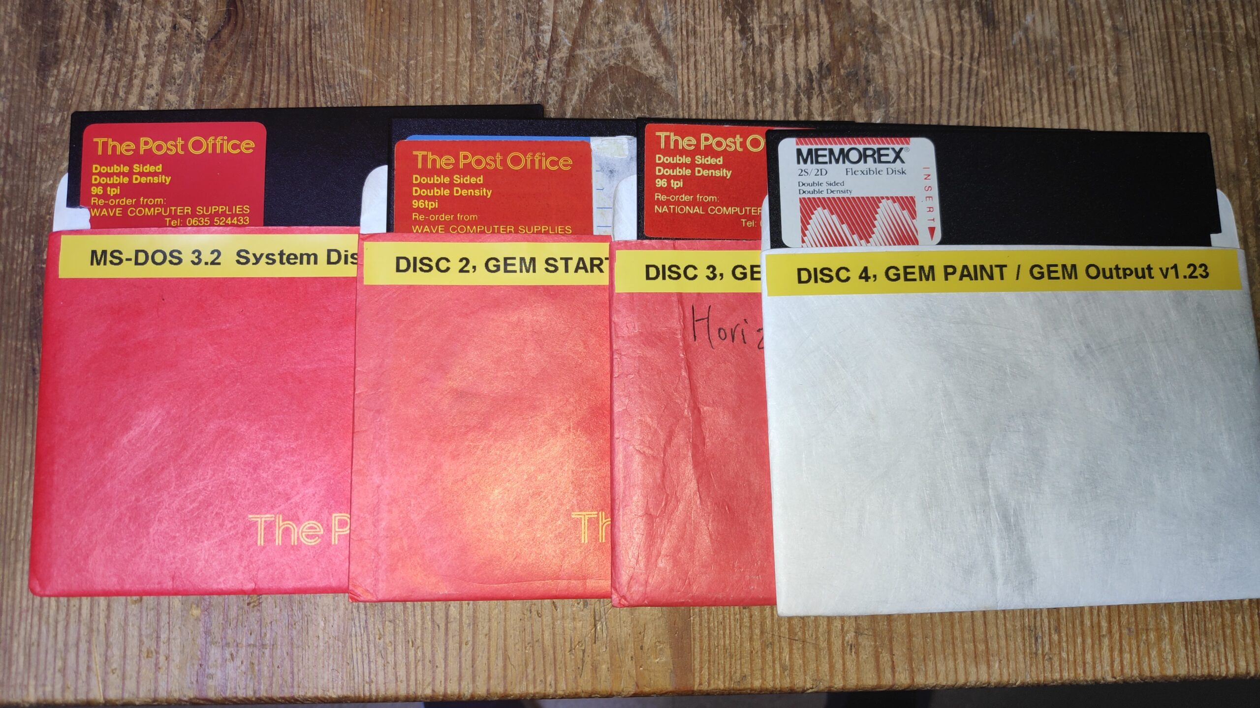
So I needed to make a set of Amstrad English disks but first had to move one of the 5.25″ drives to another machine to allow me to transfer disk image files and then create the disks.
So language issue solved.
Fill that empty coprocessor socket
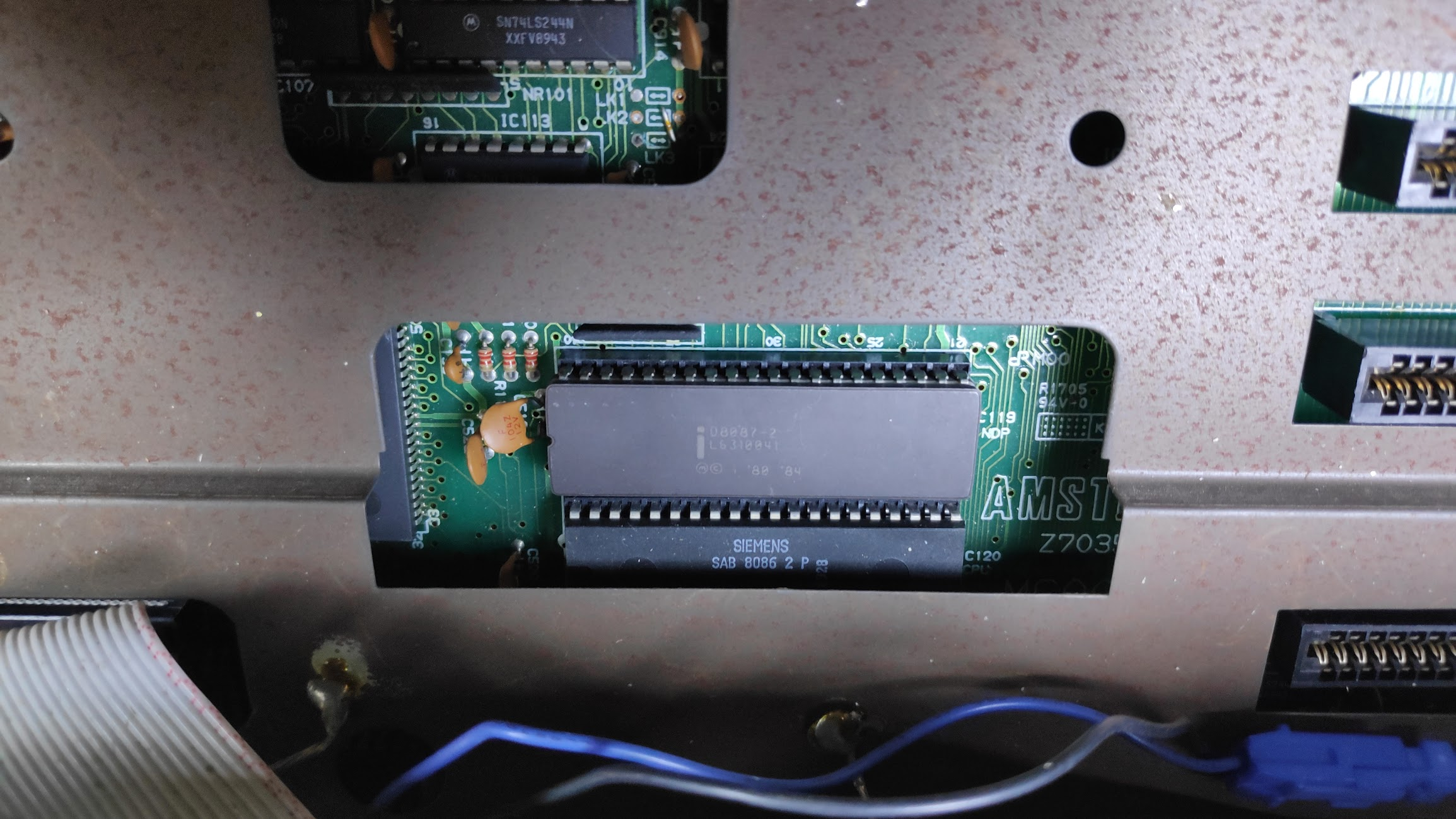
And the machine is transformed, not!. I don’t think the copro will make much difference to the performance but it will be fun finding out.
Here’s a list of software which uses it https://ctrl-alt-rees.com/2019-06-06-list-of-software-that-utilizes-intel-8087-math-coprocessor-fpu.html
I’ll try some of these later but first I want to make the machine less reliant on floppy disks as they were unreliable at the best of times and 30 years on even less so.
8Bit ISA Hard Disk Controller
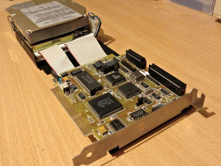
The original hard disk had the controller built into the card like this
I checked my spares bin as I remembered some cards had an IDE connector built onto the card but could only find some old 16 bit cards whereas this machine only has 8 bit slots.
Searching around the internet revealed unsurprisingly that Amstrad hard disks or 8bit hard disk controllers are as rare as unicorn poo. However I did discover some very interesting projects to resolve the issue. You can build one. Turns out there are quite a few designs readily available such as the XT-IDE by glitchworks as seen here. These actually work for most IBM PC clones with 8bit ISA slots.
And here’s the Amstrad PC1640 XT-IDE IDE Interface I prepared earlier with boards made by PCBWay
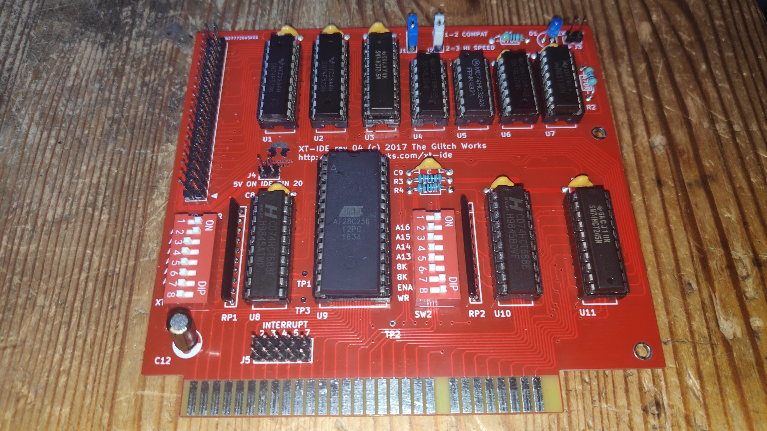
Luckily I had most of the components so didn’t take to long to build. The left side switch jumpers(SW1) are to set the port address which I set to the recommended defaults of 300H based on a writeup here. The right ride jumpers (SW2) are to set the eeprom type to 28C256 or a 28C64 and to enable/disable the rom and to enable/disable writing to it. An interesting feature of this card is the ability to write to the eeprom direct from the PC itself. As it turns out this is essential. More on this later. I have a few leftovers so just head over to the shop to buy one
I had the cable and a compact flash adapter with a 64mb compact flash.
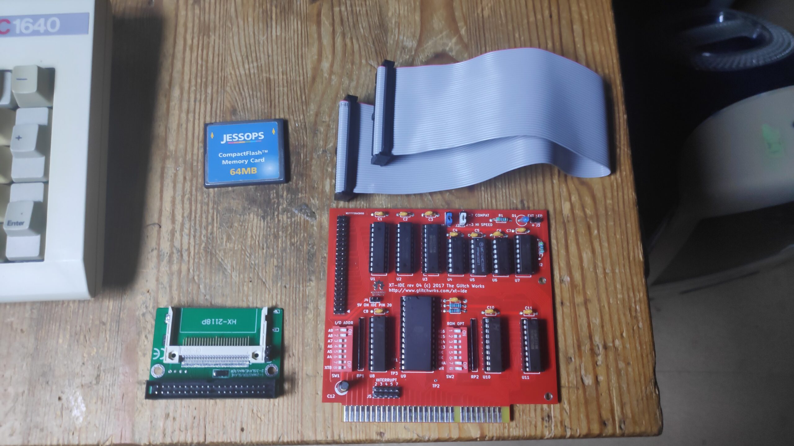
I programmed the eeprom with the corresponding BIOS file based on this page. I found the latest r629 version here. The Amstrad is a 8086 clone and I used a 28C256 EEprom so expected to program the ide_xtl.bin file but r629 only has the ide_xt.bin file so I used that. It turns out manually programming of the eprom is unnecessary except maybe to blank it. The r629 build comes with xtidecfg.com which you just run from a floppy disc.
I first installed the card with a blank eeprom and installed it all in the machine
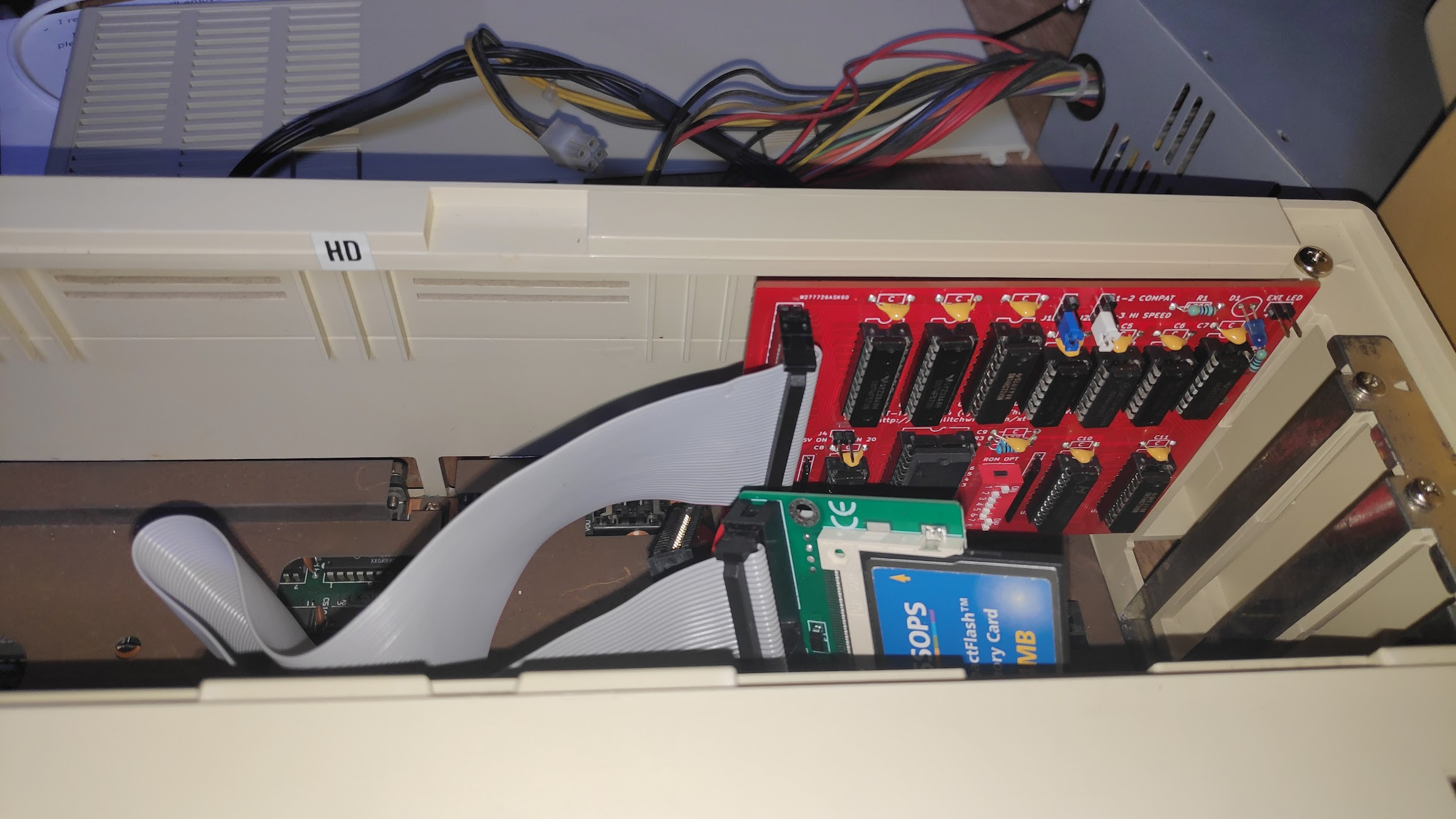
BTW the red stripe on the cable goes to the arrow on the port.I’ll make the next card with a proper IDE socket which will have a notch to ensure the cable is installed the correct way. Oh and the card is installed in the machine with the LED towards the side of the machine and the IDE towards the inside of the machine.
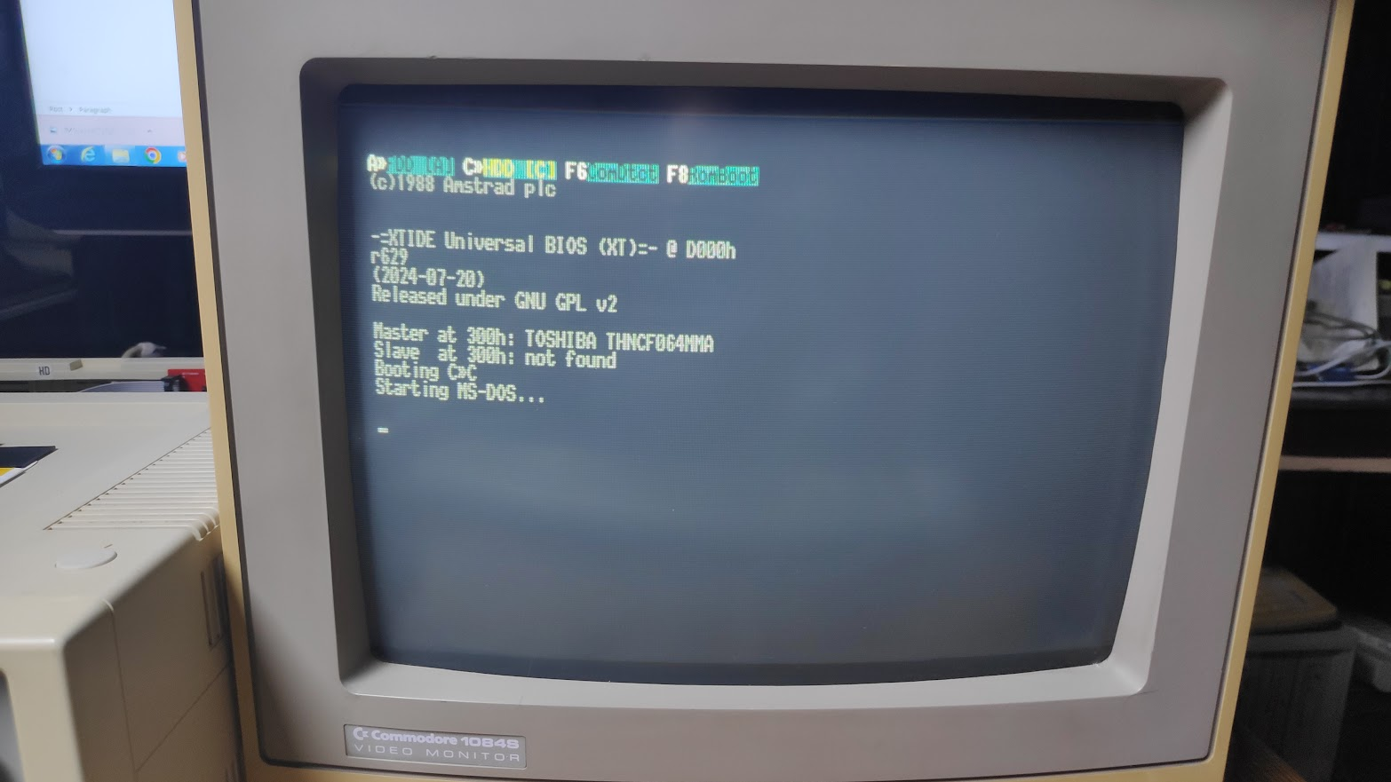
XTIDECFG
Before the card can be used we need to configure and program the eprom. A program called xtidecfg.exe will do this for us. This utility and the required universal bios file is available here.
You also need to set the SW2 switches shown below for the correct EEPROM. I have tried with 28C256 and AT28C64 EEproms. For 28C64 (8K eeproms) the 8k switches need to be set to on. For EEproms such as 28C256(32K) the 8k switches need to be set to off. I have also set enable(EN) on to enable the card and WR to on to write enable the eeprom.
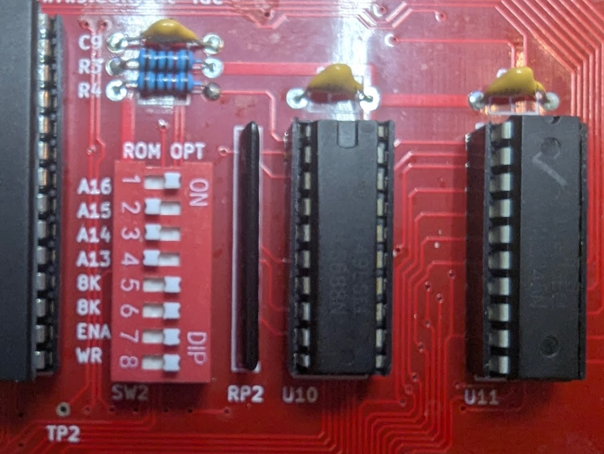
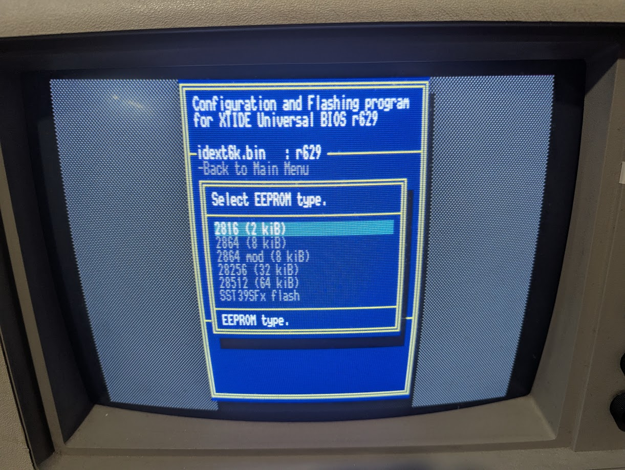
**nb I had difficulty writing to a 28C64 eprom and had to select 28256 EEPROM type in the list below and then select Flash eprom. This obvioulsy failed but when I then selected the 2864 mod the flashing worked perfectly.
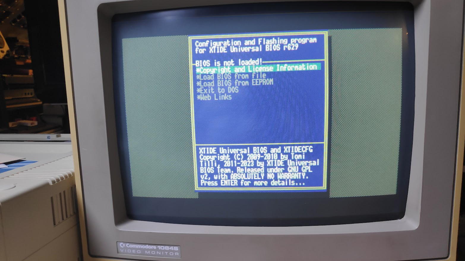
Load BIOS from file and select ide_xt.bin
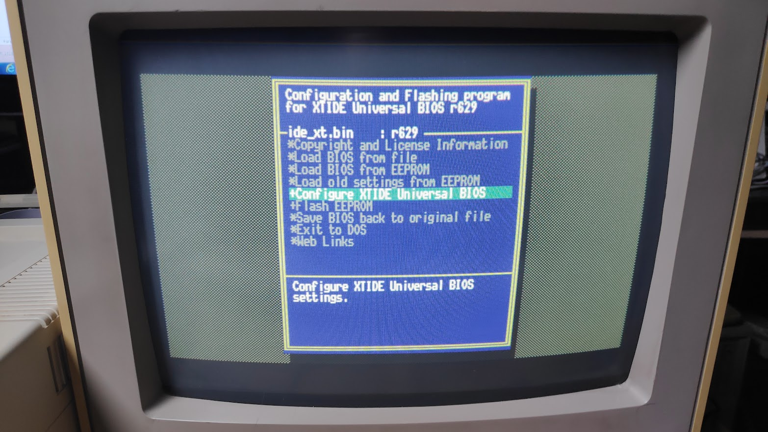
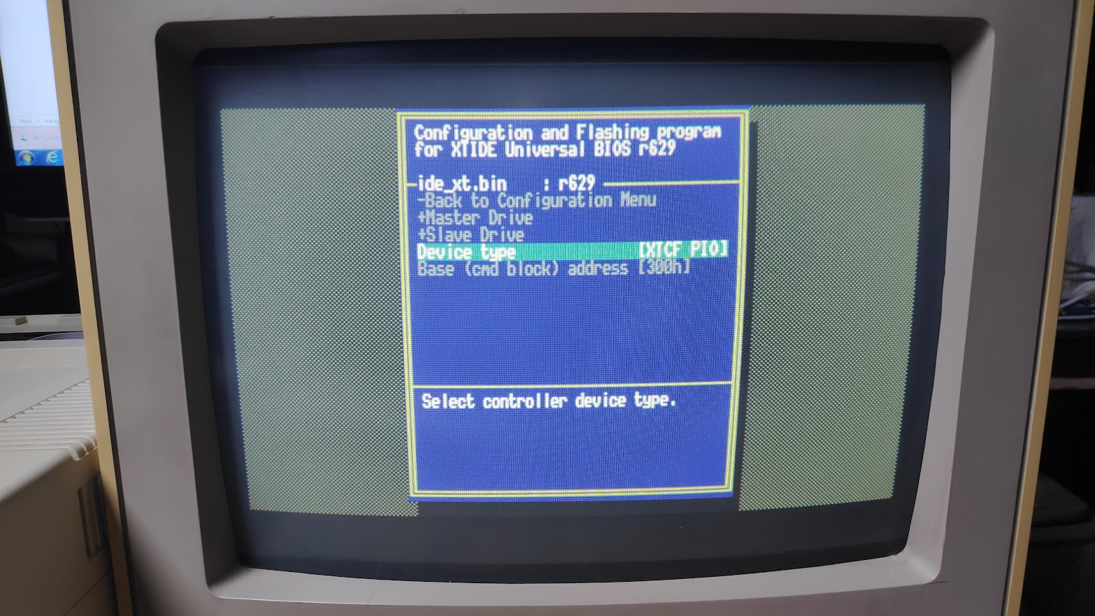
Select “Configure XTIDE Universal BIOS” then “Primary IDE controller”. XTCF_PIO with block address 300h was selected by default. Didn’t change anything and returned to main menu.
Next select Flash EEPROM.
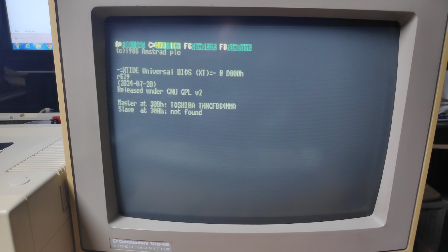
The start flashing and its all done. Reboot the machine and the compact flash adapter should be detected.
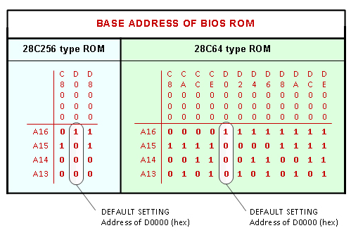
Below is a diagram which shows the base address setting for 28C64 and 28C256 EEProms with the SW2 switches on the card. Just make sure to set the same address when flashing the eeprom.
FDISK
I still had to boot from floppy to setup the hard disk.
Now what was the command I used to use? oh yes FDISK. Its been a while….
I haven’t used fdisk in decades but I remembered the basics setting up a hard disk. Wipe any existing partitions, create a new partition, set active partition, format the partition.
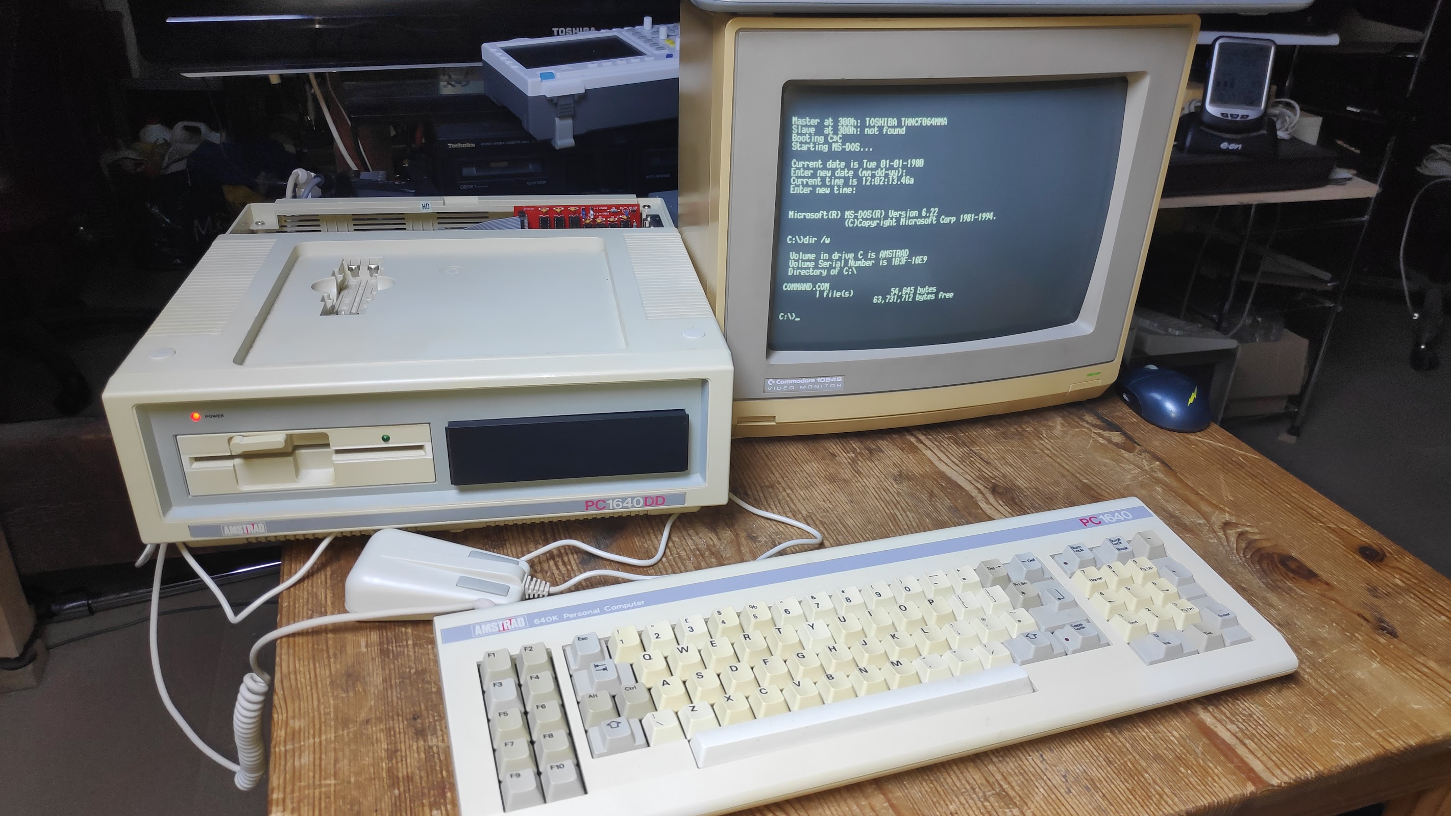
Unfortunately Amstrad 3.2 DOS is not up to the job for hard disks greater than 20Mb so I made a 6.22 dos disk which allows upto 8GB drives.
Now the DOS 6.22 fdisk would allow large hard drives to be created
After creating the new 61Mb partition in fdisk I was asked to reboot.
I formatted the compact flash disk with FORMAT /S which copies the bootable dos system files to the drive after formatting.
On rebooting sadly the system would just hang with this.
However looking into the Common issues it was suggested to run fdisk /mbr.
Finally the system booted from compact flash.
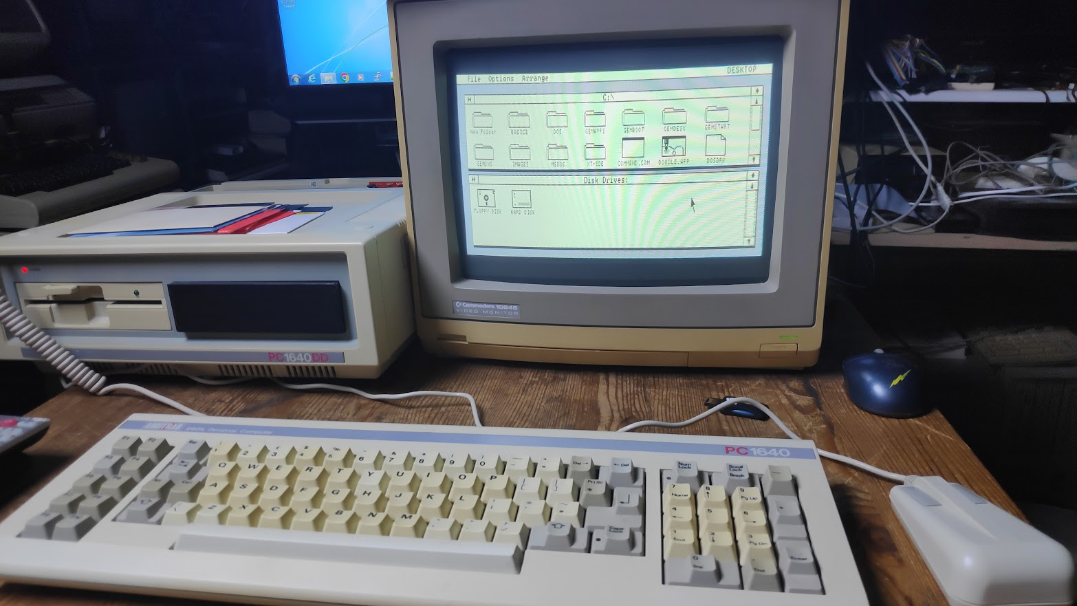
GEM Install
I wanted to install gem but it wasn’t immediately obvious how to do this from the disks so a bit of research revealed that on Amstrad Disk 4 there is a file CONFIG.BAT which installs GEM to the hard disk. Unfortunately this also installs the unwanted 3.2 dos to the directory MSDOS. Luckily I had installed my dos 6.22 files to the C:\DOS directory. Also the config.sys and autoexec.bat files had been overwritten but I easily reset those back using the rped editor.
Typing GEM after booting from the hard drive now comes up pretty quicklybut the mouse buttons don’t work using the original mouse 5.0 driver that came with Amstrad DOS 3.2. I found a newer 7.04 version which works with the mouse buttons.
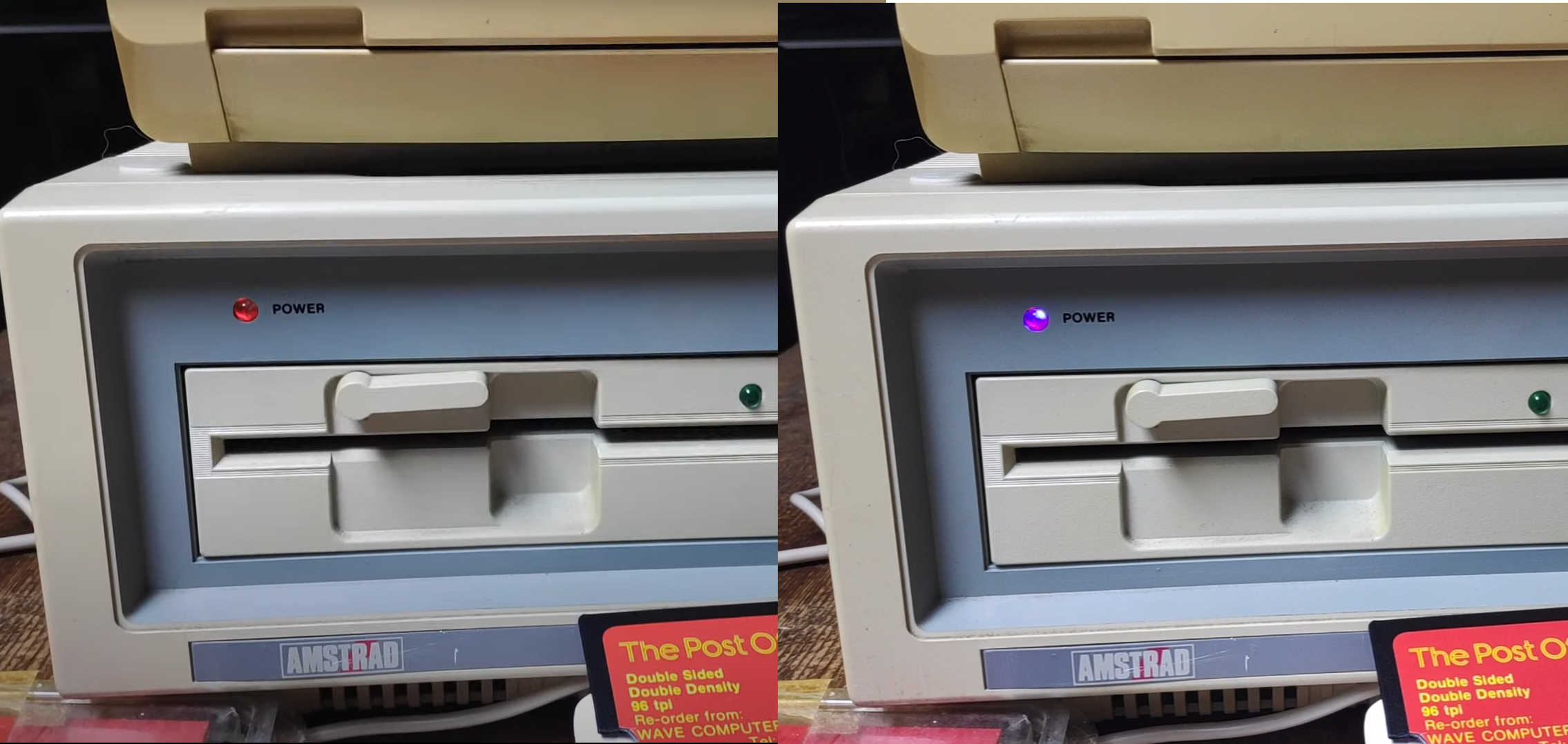
External HD LED
It would be nice to see when there is hard disk activity or rather Compact Flash activity. The XT-IDE card has 2 pins top right marked Ext LED
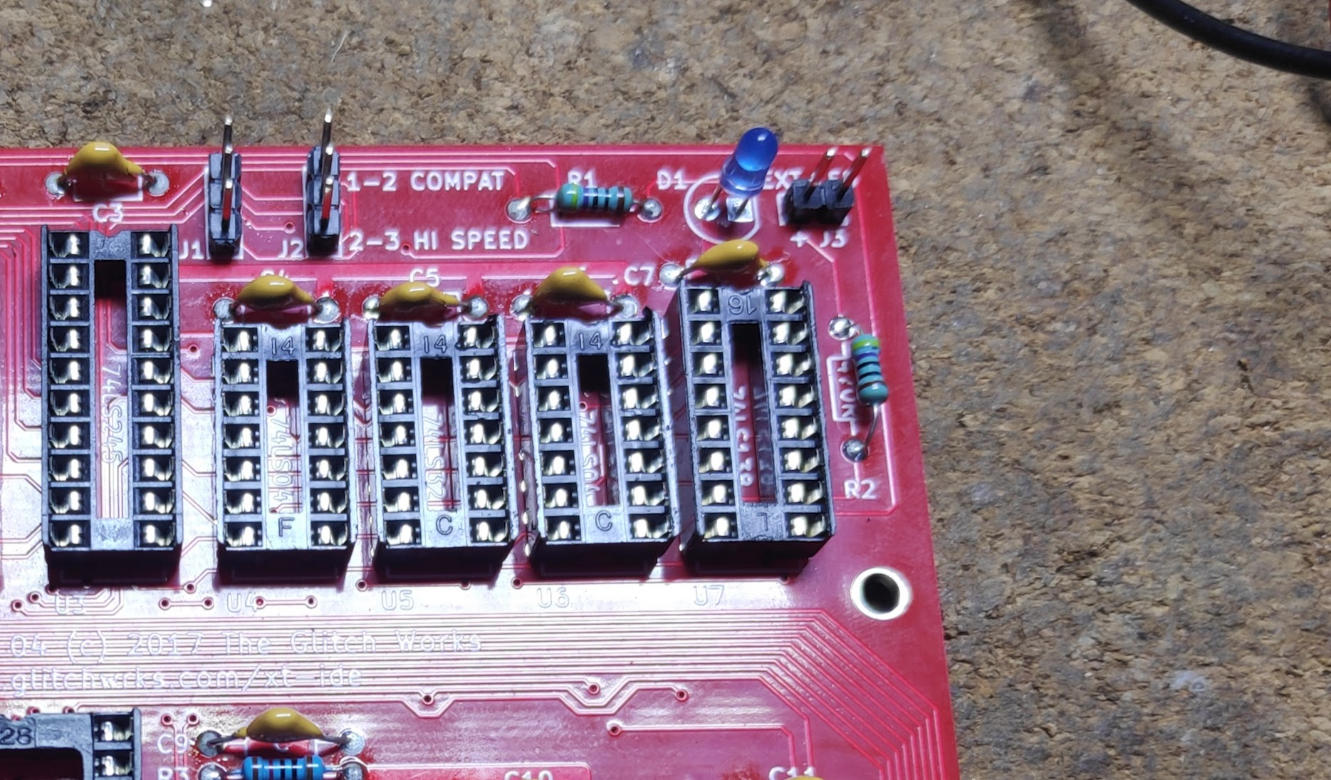
So I connect a 2 wire cable with a nice bright blue LED but where to put it?
I could have drilled a hole in the drive bay blanking plate but I didn’t want to spoil it and I was toying with the idea of installing a Gotek in this bay as 5.25 disks are not the most reliable being 35 years ish old. I therefore experimented with placing the LED next to the red power LED but it was not visible. After some tinkering I found the best option was to put the blue LED in the power LED hole and put the power LED next to the BLUE LED. This allows for the blue LED, purple as a result of the red blue mix, to be visible during disk activity and when on no disk activity the red LED although a little dimmed is still visible.
Gotek Install
Its been a while since I installed a Gotek. I’d installed lots of these with Amigas and Atari ST’s and most recently an Acorn Electron with a plus 3 which was a little tricky but not too difficult. All those Gotek’s used the old STM chip but the Gotek’s I just bought now uses a cheaper Artery chip. I must admit I neglected to check which chip version I was getting on purchasing. It turned out to be the AT32F415 which has limitations such as no track formatting and can’t write to high density HFE images but these features are not required as the Amstrad FDD controller is limited to 720k and I will not require formatting as disk images will be premade and transferred from a PC to the USB stick. The AT32F435 has these features if required. Anywho this GOTEK is good enough and flashing has advanced enough over the years to just program it with Flashfloppy using a jumper and a USB-A to USB-A cable as described here. I also purchased a larger 0.96 OLED as there was plenty of space on the 5.25 blanking plate. I decided to 3D print a plate and base for the Gotek but I only had a bit of white PLA left so butchered the 3D model so I could print the front plate and base separately in different colours.
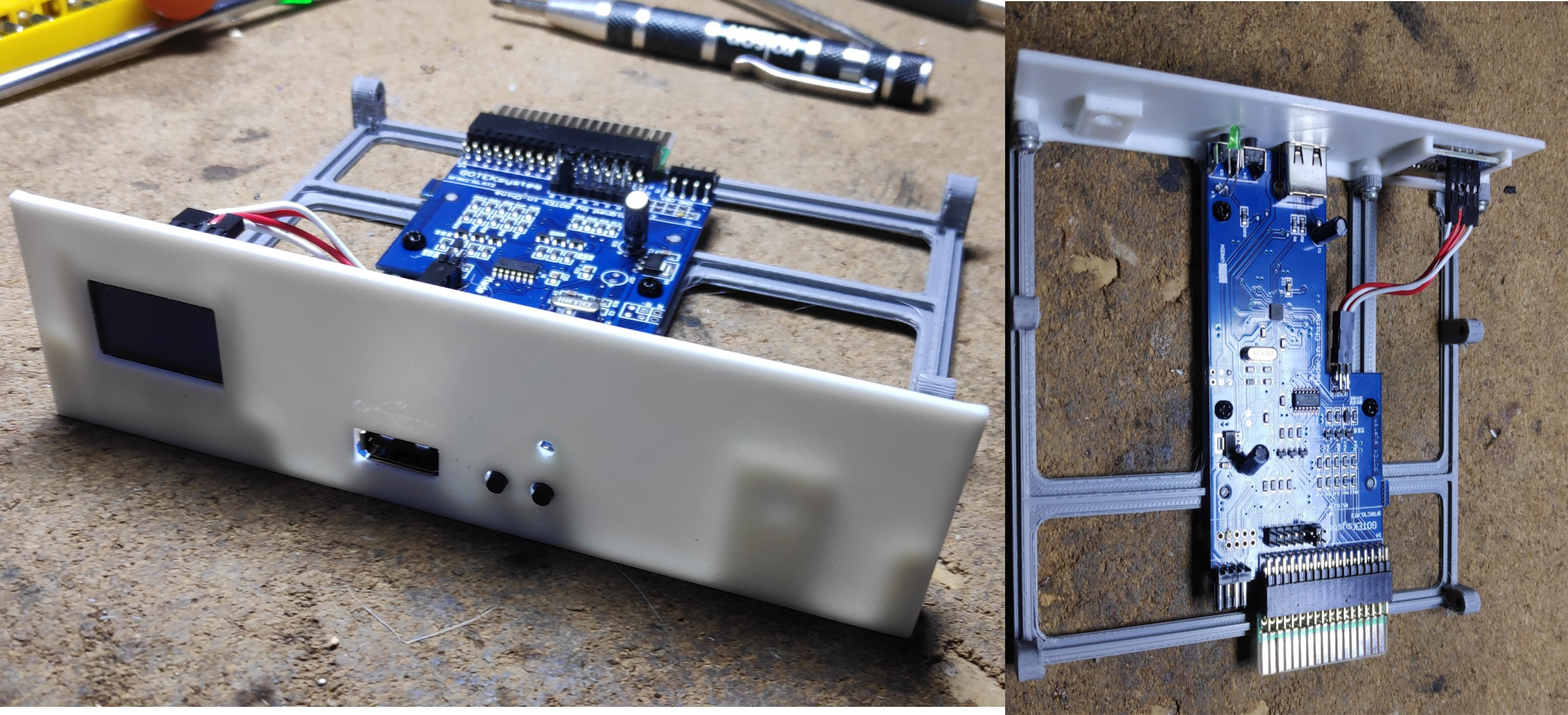
It ended up ok on the first attempt but I will probably revisit it to move the HD activity LED to it and also if I can find a long enough IDE cable, site the compact flash card here so it can easily be removed when required.
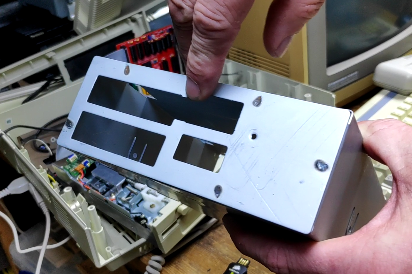
Fitting the Gotek into the machine was a bit of a pain as the floppy cable wasn’t long enough to reach so I had to modify the caddy slightly to allow the cable to take a little shortcut.
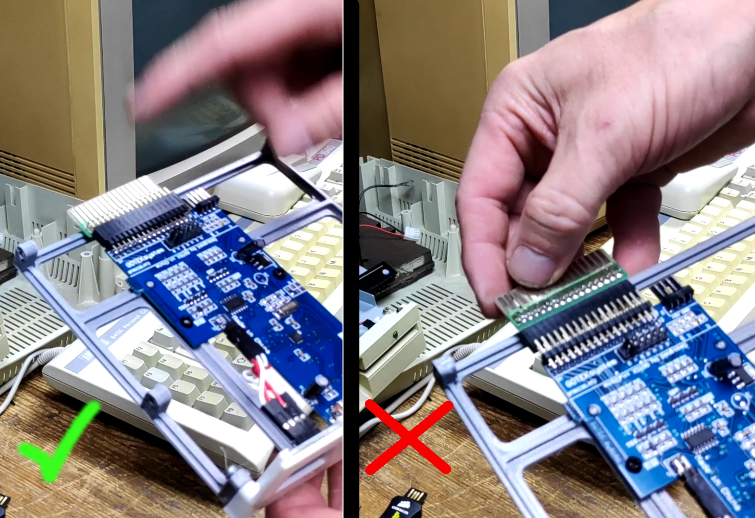
Another issue is the Amstrad floppies connect with an edge connector but the Gotek is a 34 pin connector but I had an old adapter. Testing with the adapter wouldn’t work until I installed it the right way. IDIOT!. The adapter should be installed as follows with the soldered pins on the underside.
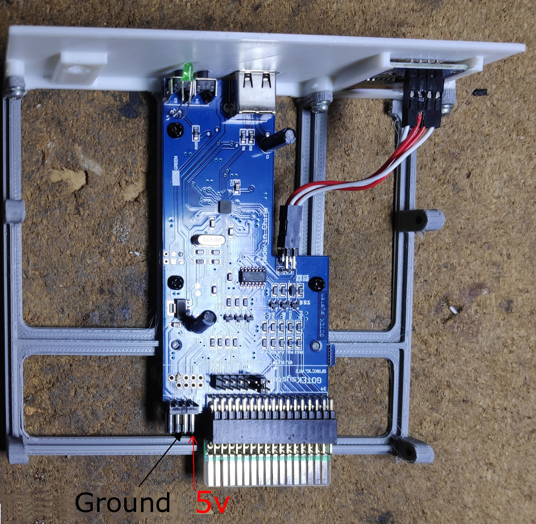
The Gotek is powered by a mini molex floppy connector so I had to splice into the existing molex cable as I didn’t have an adapter. 5v is the left most red with the midle two pins ground as shown. It is also marked on the Gotek board.
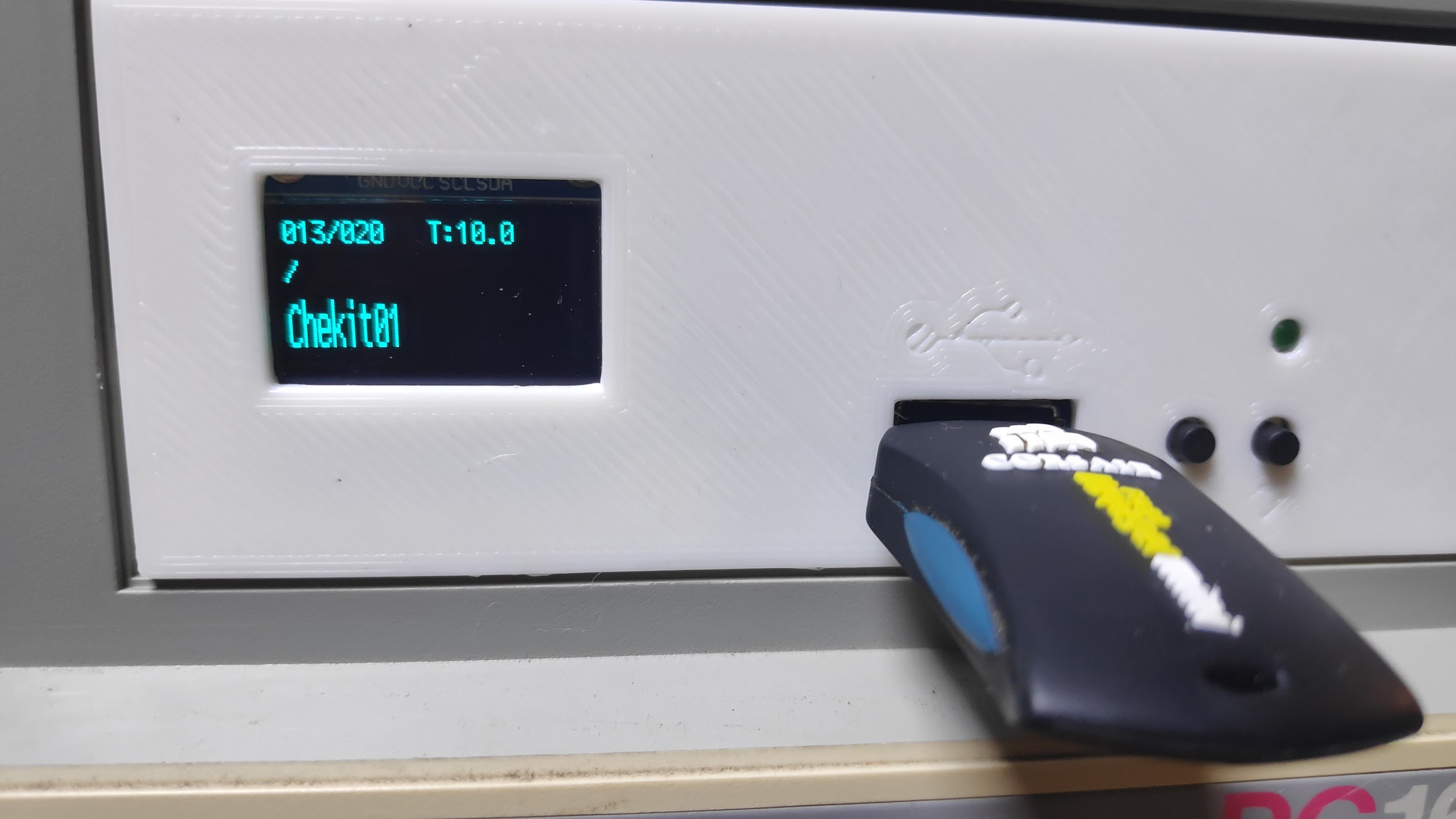
The OLED is easily configured in the flashfloppy FF.CFG file. Set the pixel resolution and how you want each of the three rows displayed. I chose Status row 1, Folder row 2, Filename double height row 3. This configuration is described here
display-type = oled-128×64
display-order = 1,3,0d
The next issue was the length of the FDD cable which wasn’t quite long enough to reach the Gotek and also the power
Installing software
This is a pain with disks. Installing Gem took about 10 minutes. The best way is to just remove the compact flash card and stick it in a PC then just copy files over. The problem is where there needs to be an installation process but Dosbox comes in handy for those situations.
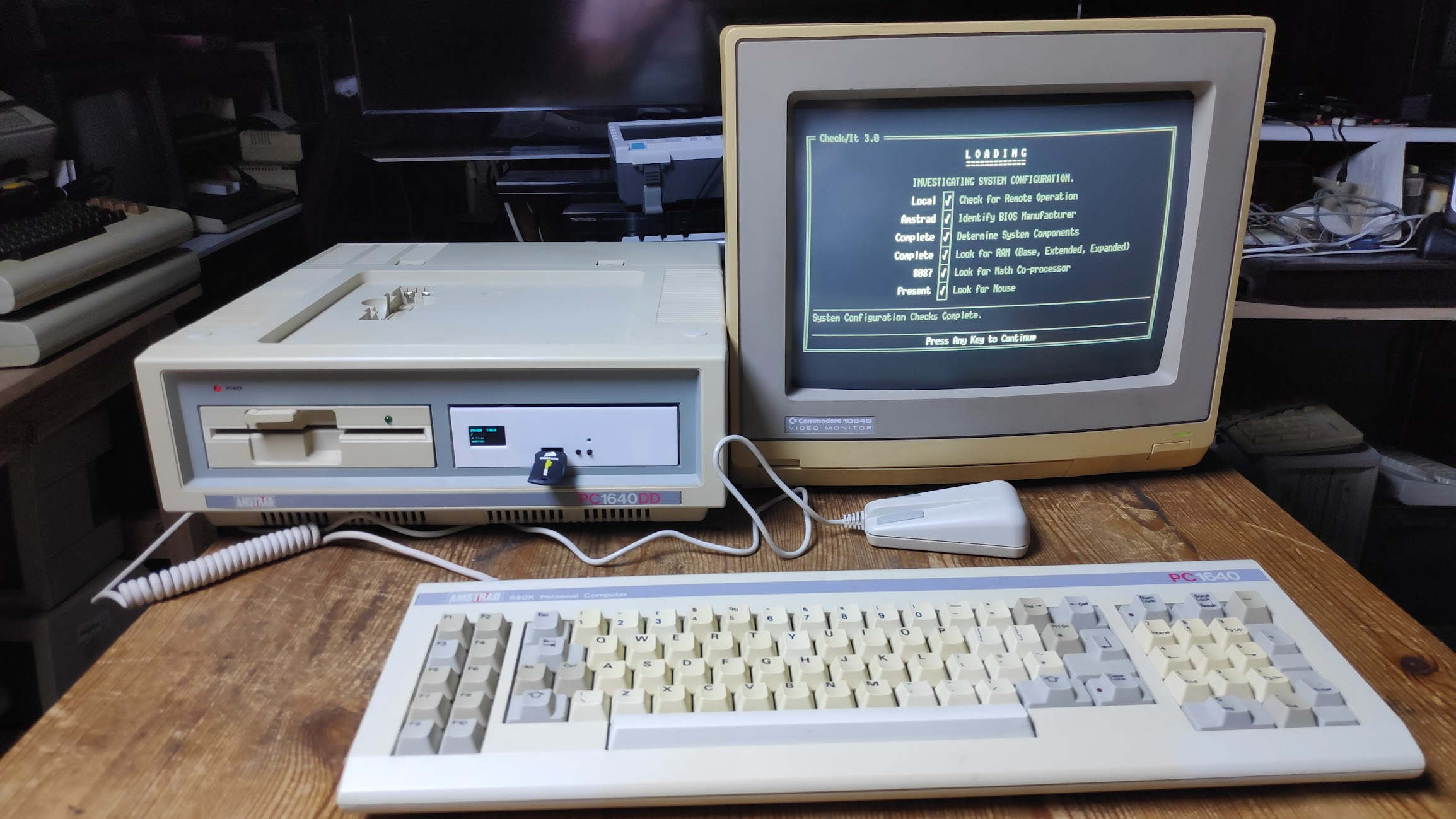
I installed checkit which confirmed the maths coprocessor was being detected.
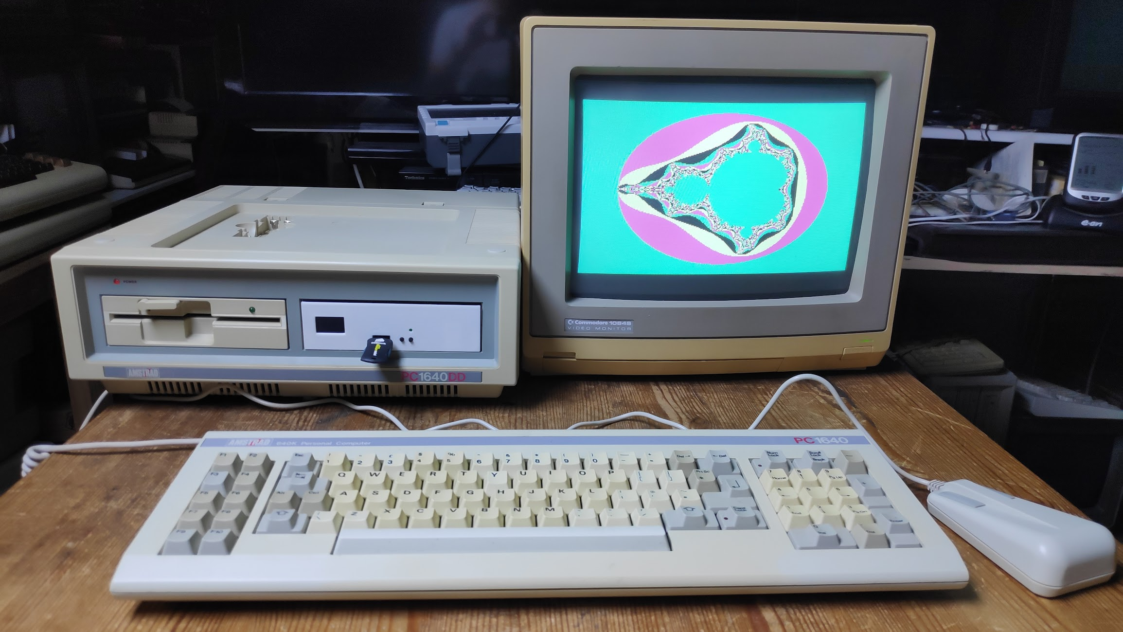
I just copied software onto the compact flash card such as Fractint which uses the maths coprocessor. Seems to work a little faster. I used to spend hours playing with Fractint. I was fascinated with the ability to infinitely zoom and find interesting images to save along with various resolutions and colours to optimise speed. In later years with 386 and 486 machines I would expriment with making fractal zoom videos.
The XT-IDE really transformed this machine and I have some leftover cards ready made to just plugin and go here if you want one
Next Steps
Play some games
Move compact flash to Gotek face plate.