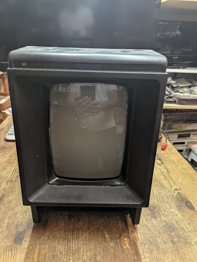
This is a Very Dead Vectrex Repair and yes I am praying in the reflection that I can save it 😉
When I got this home I had a look inside and quickly closed it up as it was not a pretty sight. It broke me out in a sweat it was that bad so I decided to tackle it another day……
Three years passed…
I heard from a friend that Elite is available for the Vectrex and thought, Its time….
I gave it a casual clean and opened it up. Then looked for any capacitor leakage or scorch marks from failed components but all “seemed” ok.
So I powered it on and…..
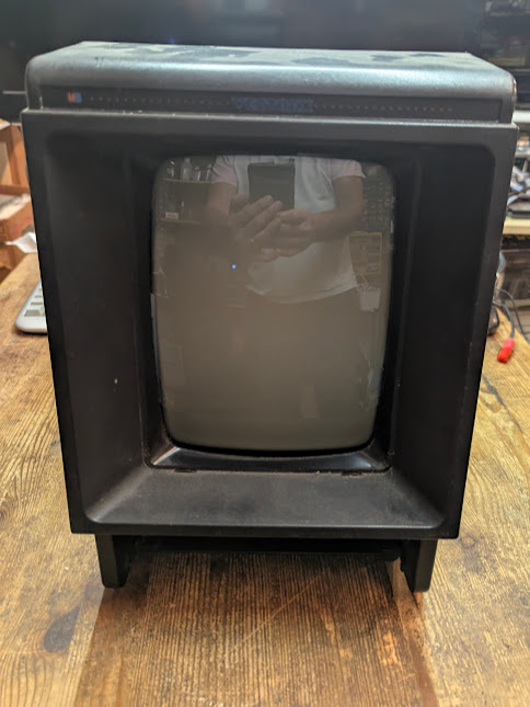
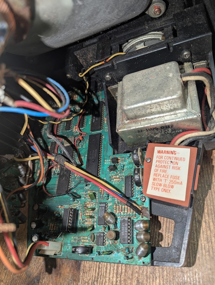
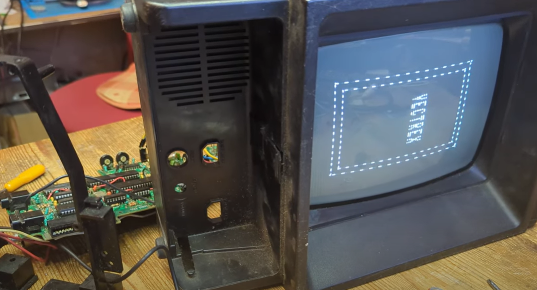
Nada, no sound no display nothing. But wait, I’ve just noticed on this image from a few days back. It looks like there is a dot on screen or is it my watch reflection? I didn’t notice anything at the time. I checked the fuse beneath the Warning label in the image below, it was fine.
So what about the dot?
Was it plugged in at that point? I can’t see a power cable leading off the table to the right. Oh well I’ll carry on with my assessment regardless.
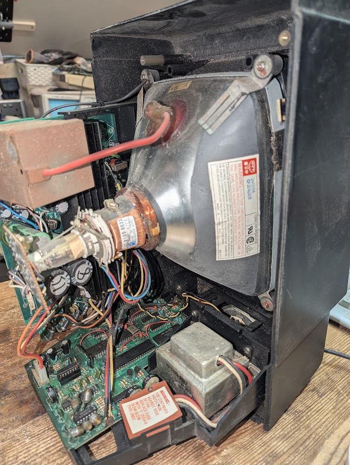
The Insides
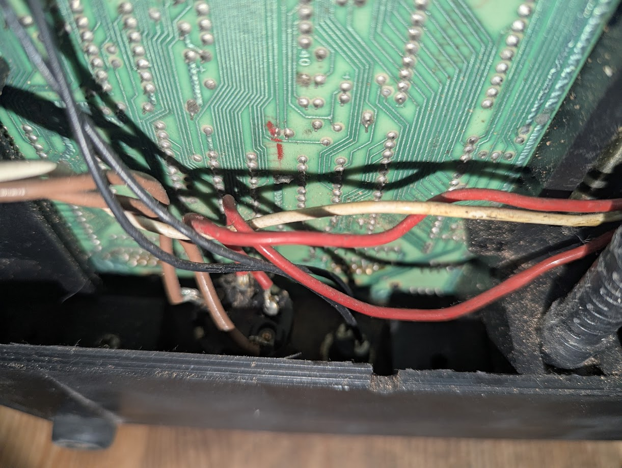
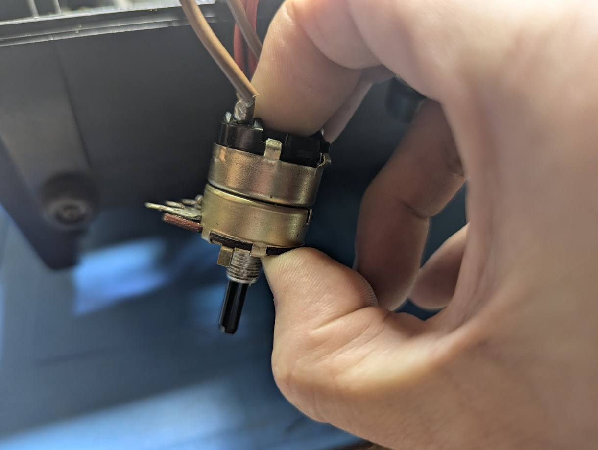
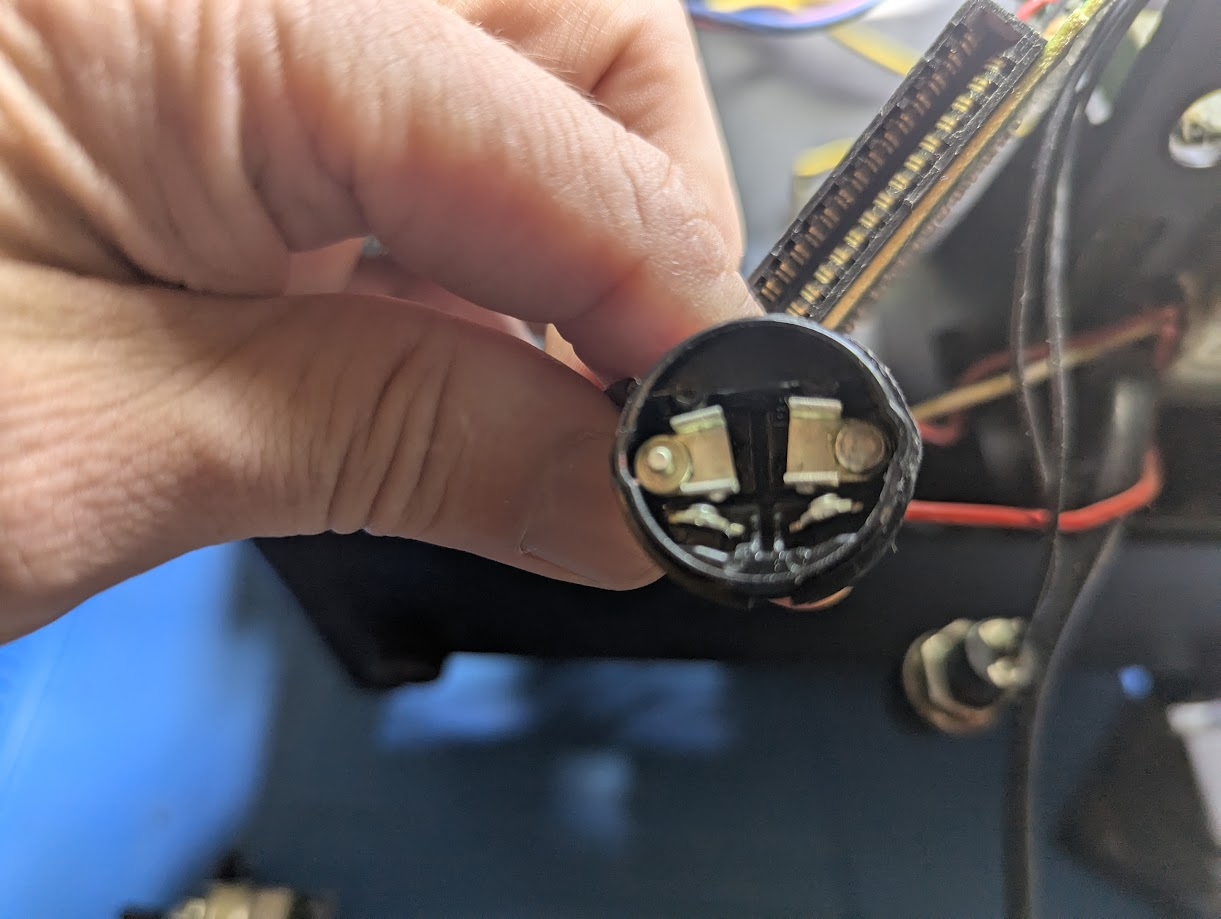
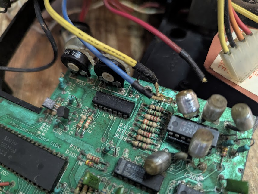
There definately is a power switch issue as only half the wires are showing continuity when switch on. As seen below the power switch provides continuity from red to brown. There are two pairs and only one of them is providing power.
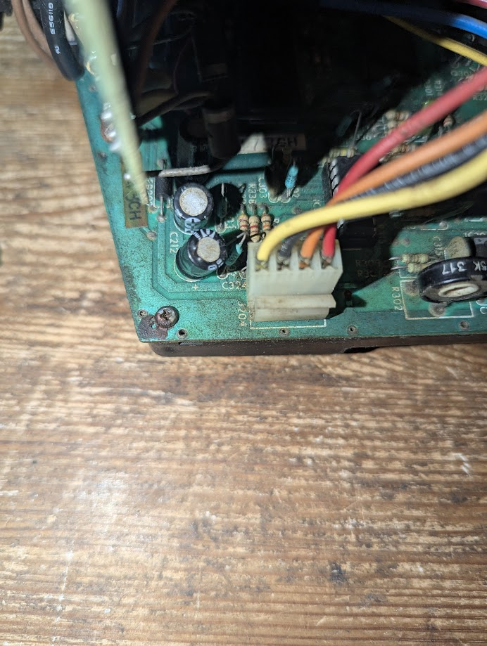
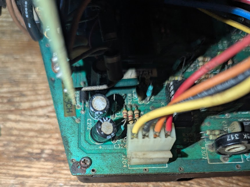
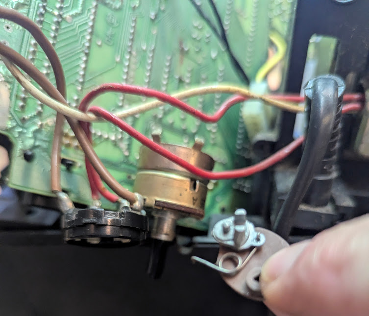
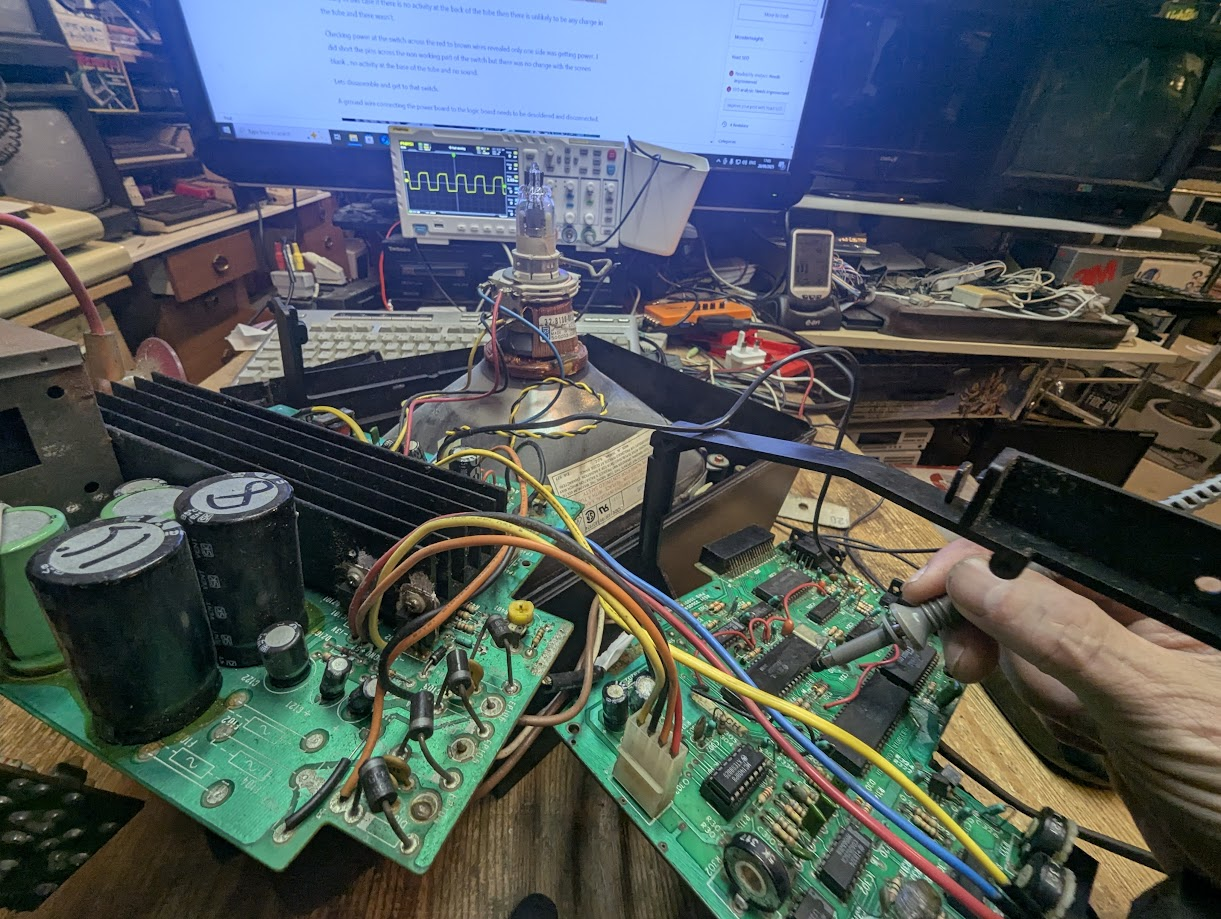
When powered on there is power to the logic board as there is -5v (Yellow wire), +5v (Orange), -13v (Red) at the connector in the image below so some power is getting through.
There is no sound or buzzing when switched on and I don’t notice any dot or anything at all on screen. The tube at the back isn’t lighting up so the dot must have been either a micro ghost or a reflection.
Tube Discharge
Courtesy tube discharge. WARNING there is a serious risk of electric shock doing this unless you know what your doing. Pacemaker people, please don’t try this. I always wear rubber gloves when tube discharging and should actually only be using one hand to discharge as the shock could go across your chest. Here we go.
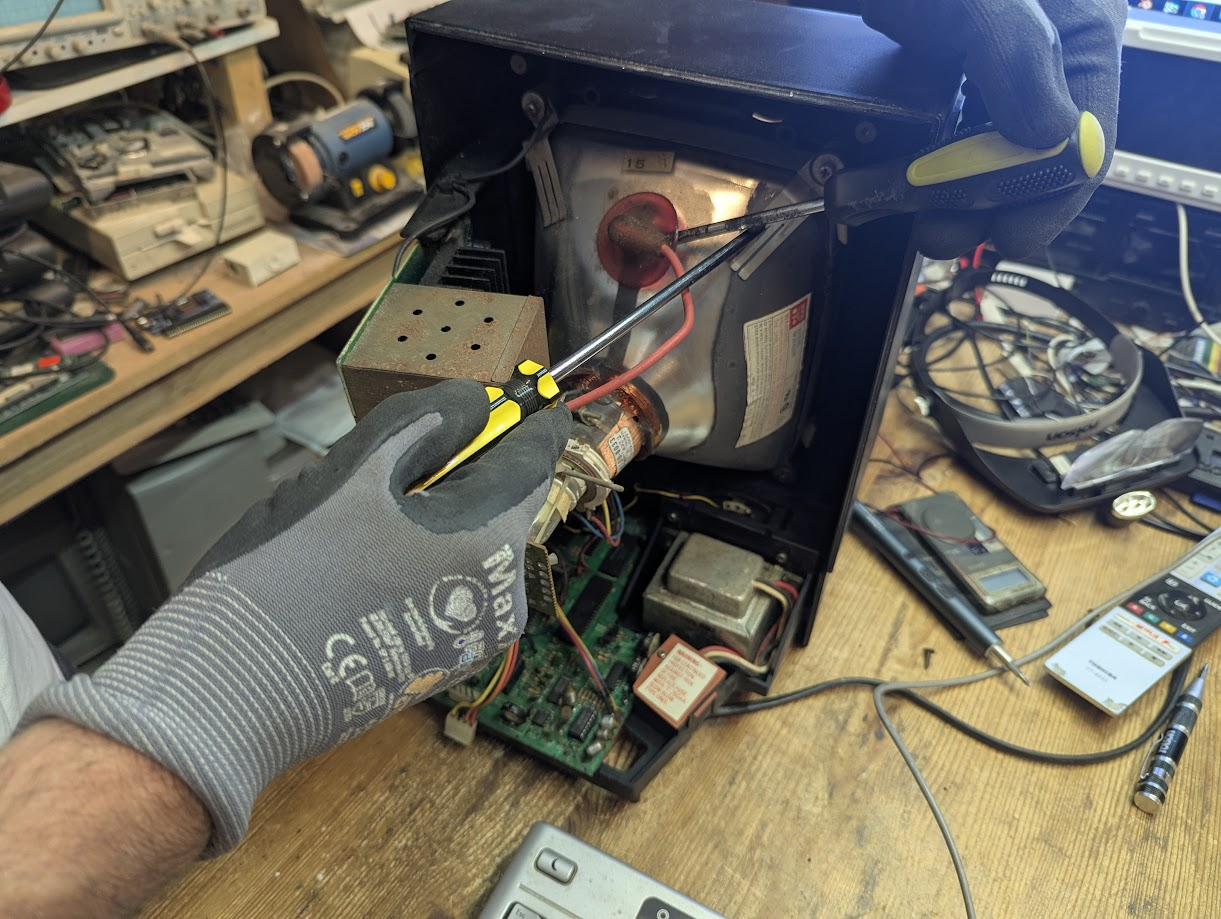
Actually in this case if there is no glow from the neck of the tube so there is unlikely to be any charge in the tube and there wasn’t.
Checking power at the switch across the red to brown wires revealed only half the system is getting power. So I shorted the pins across the non working part of the switch but there was no change as the screen remained blank, no sound and no activity at the neck of the tube.
Lets dissasemble and get to that switch.
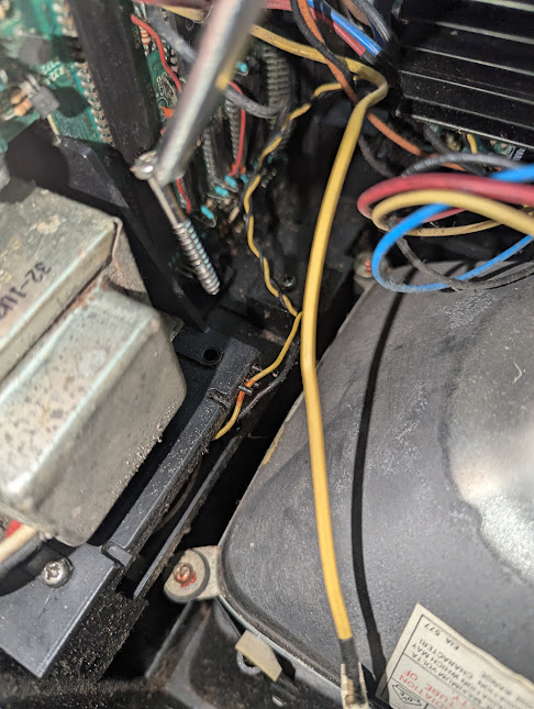
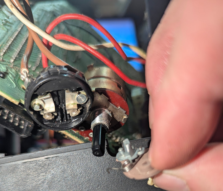
A ground wire connects the power board to the logic board needs desoldering to disconnect.
There are four screws around the transformer to remove
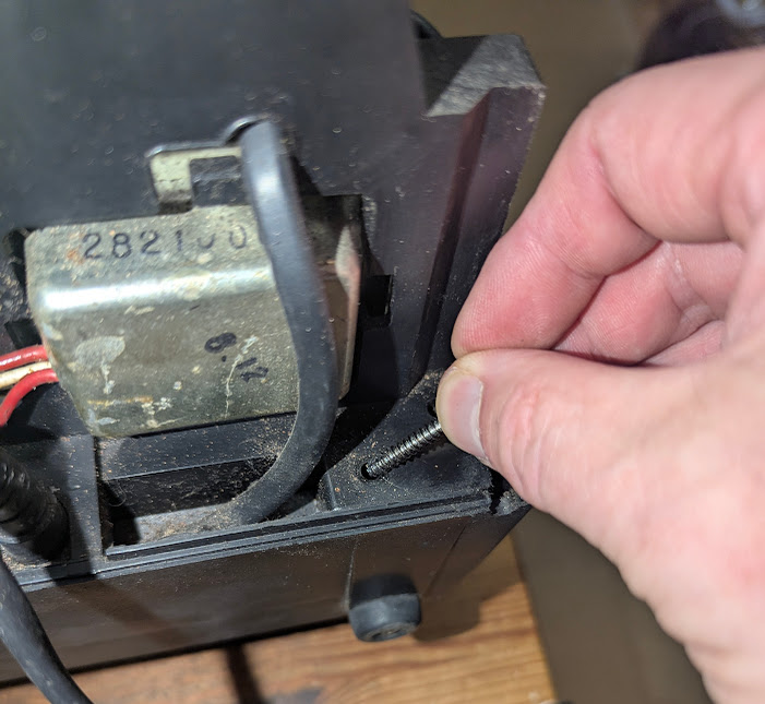
A screw next to the power switch
A couple of screws on the logic board
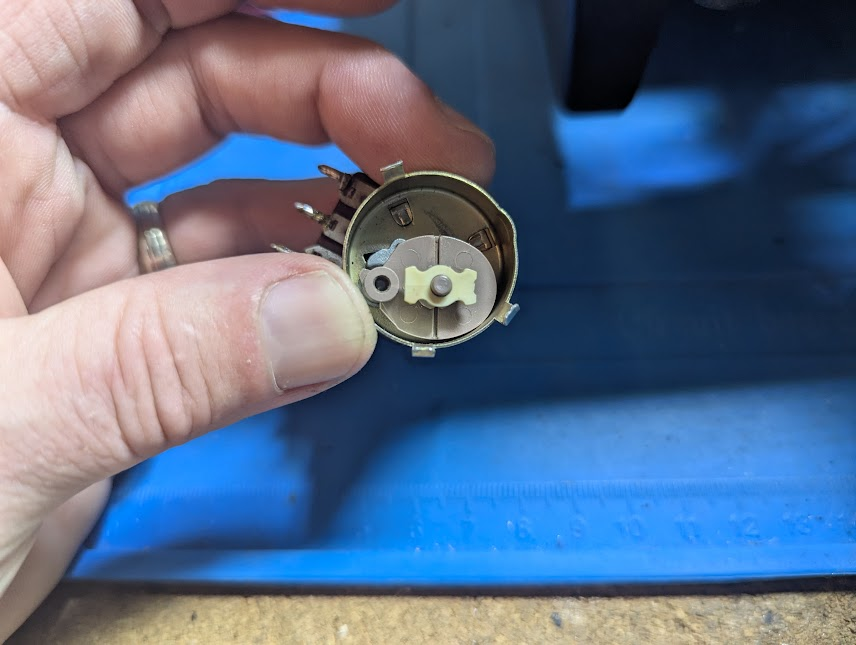
The Power Switch
With the logic board removed desolder the power switch. This allows access to the metal tabs at the top. These are pryed away from the black plastic top to release.
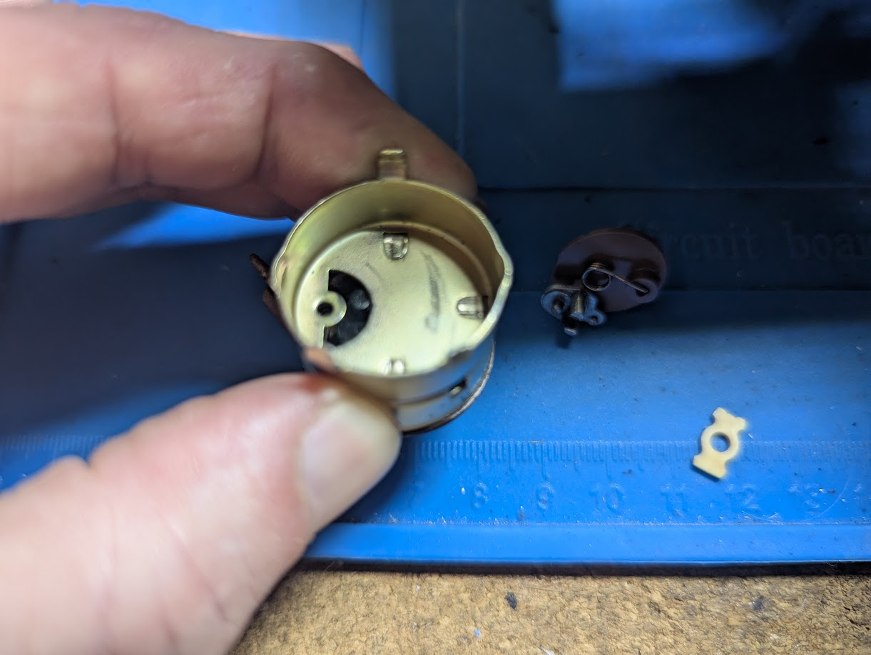
With the tabs opened the black plastic top simply lifts off but be careful as there is a sprung connector inside.

The sprung connector can easily be lifted out with the dog bone latch which fits into the contacts shown below.
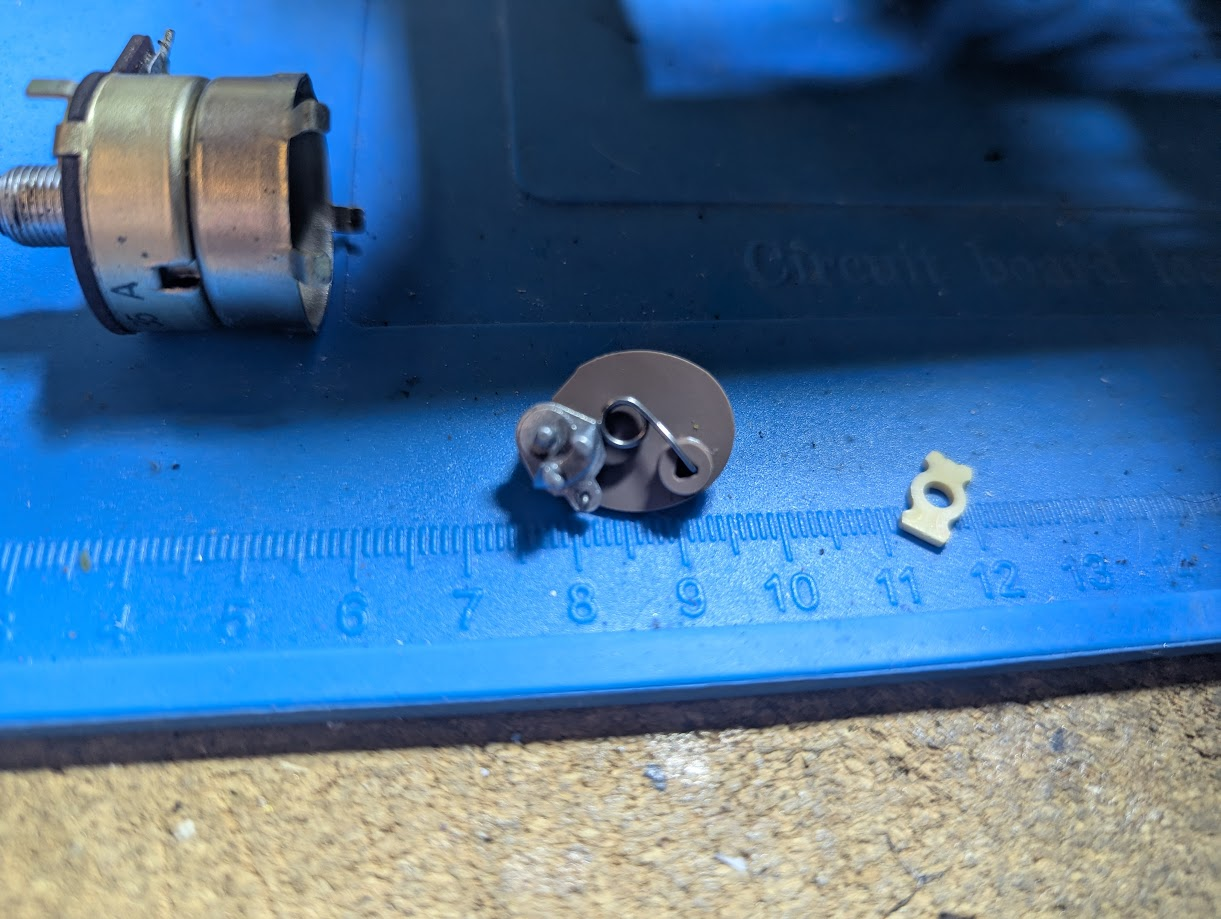
Below shows the grey sprung connector in the on position aligned vertically.
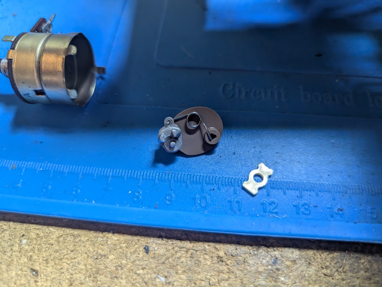
And here is the off position. The grey connecter is in the south east position. This position is required for reassembly
The contacts are quite gummed up. A good clean with alcohol and contact cleaner sorted it. Additionally a bit of light sanding of the contact points by sliding a bit of 2000 grit wet and dry between.
Power Switch Assembly
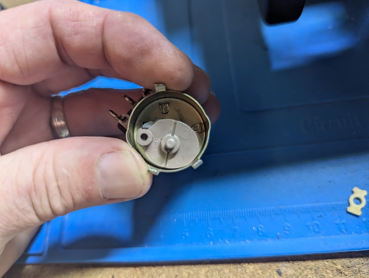
Reassemble by setting the switch to off with the black plastic peg visible through the crescent slot.

The sprung connector set to off as described above needs to be placed with the metal part inserted in to the hole and crescent slot. It is held in place by the spring which is off center so remember this as the black cap must be maneouvered so the near central peg is moved to the center.
Put the dog bone back on in the horizontal position.
Now the tricky bit. Orient the black cap to align with the metal tabs. As stated the grey metal connector is sprung off center and its peg must be inserted in the hole in the beige plastic above at an angle and as you close the cap move it to the center. With black cap closed on the metal housing you will feel the sprung resistance when turning the volume shaft and this moves the grey inside connector to the on off position. The cap should align with the tabs ready to clamp.
Before claimping the tabs back firmly hold the black cap on while turning the switch to on. Check that the switch clicks while doing so. You can also check continuity at this point but you must make sure to firmly hold the cap in place. Once verified continuity then move the clamps in place. Turn the volume shaft clockwise to turn on. A click will be heard. If no click is heard then remove the cap and reseat the grey plastic connector and try again.

With the switch repaired its best to leave it on and just use the mains plug socket to switch the unit on and off. Its ok to use the volume just don’t turn it off as the grey connector may come out of position and need reseating. The transformer actually remains powered even when the the switch is in the off position so never a good idea to leave the power on at the plug with a Vectrex.
Broken wires
One of the wires came off while fixing the power switch and the others looked brittle and ready to break off so I decided to make a connector to easily disconnect and connect these wires
Removed the wires and cleaned up the holes
Need to strip the red wire back. Pin headers ready to be soldered in.
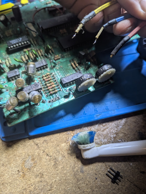
Connector finished
Need to make a red mark to signify which orientation the plug is connected.
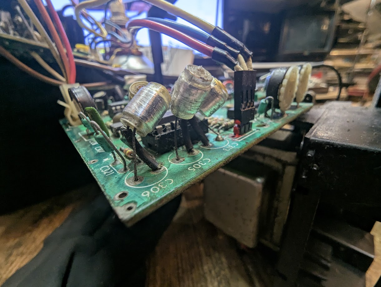
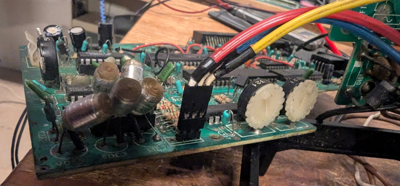
Power Transformer
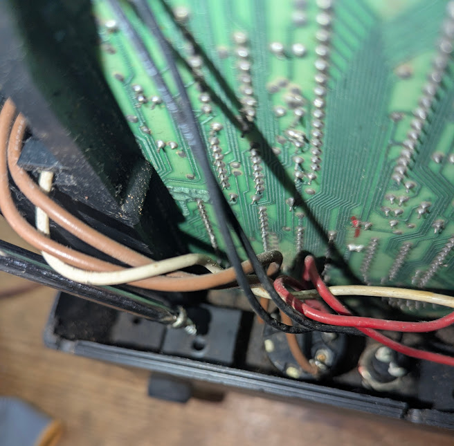
The power transformer is a common source of failure. I checked transformer secondary voltages on power board. The brown and white wires from the power switch connect to these diodes EP104, EP105(Center white), EP106
First EP104(Brown wire) to center 10.7v
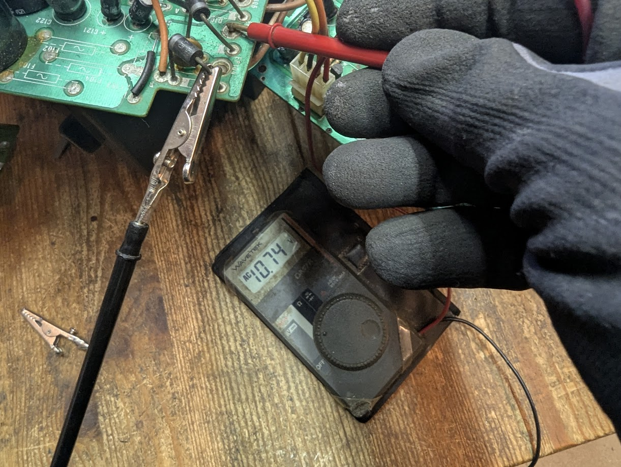
EP106 (brown wire) to center.
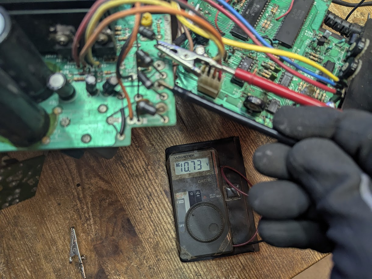
10.7v on both sides so transformer looks ok.
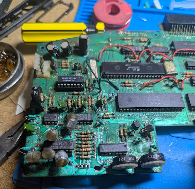
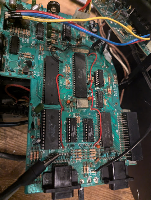
The Logic Board
With the boards removed I can more easily work on whats wrong. I checked for a clock signal pin 34 on CPU
Looks good. I’m not sure the Vectrex is still very dead as this repair has sort of rendered it undead. Life signs are very faint.
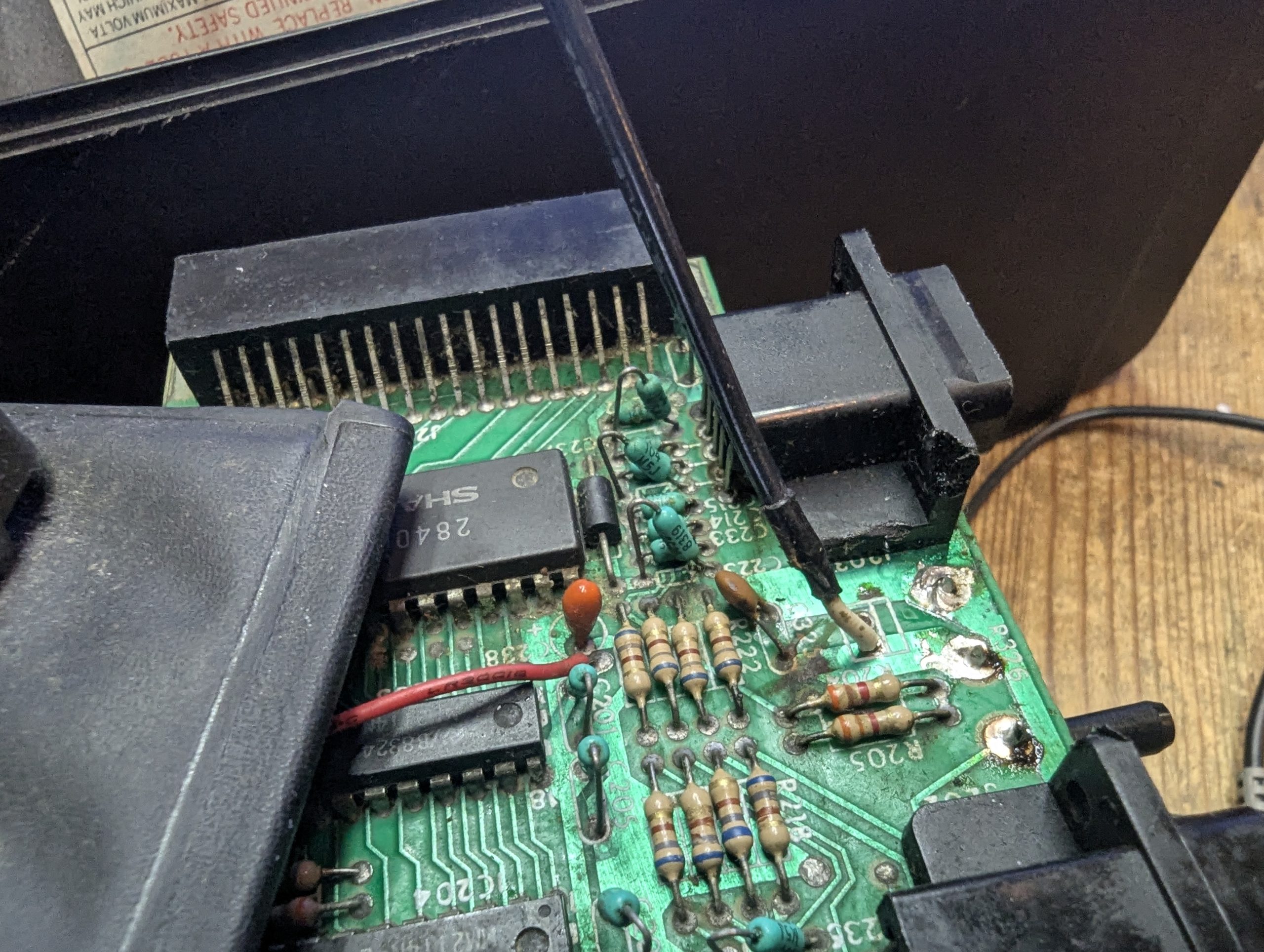
Went through all the chips checking 5v and found the sound chip IC208 is showing only .2v on pin3.
I use this tool called openboardview which really makes this process so much easier and its FREE!. For any retro troubleshootists I fully recommend this if you can get a BRD file for whatever your troubleshootisting.
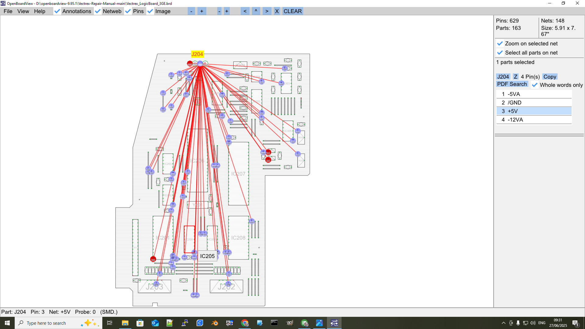
5v lines check ok except….
IC208 AY Sound chip pin 3 which shows .2v
Socketed and replaced it from a doner Spectrum +2A. The AY sound chip now shows a healthy 5v on pin 3 but still no life from the Vectrex.
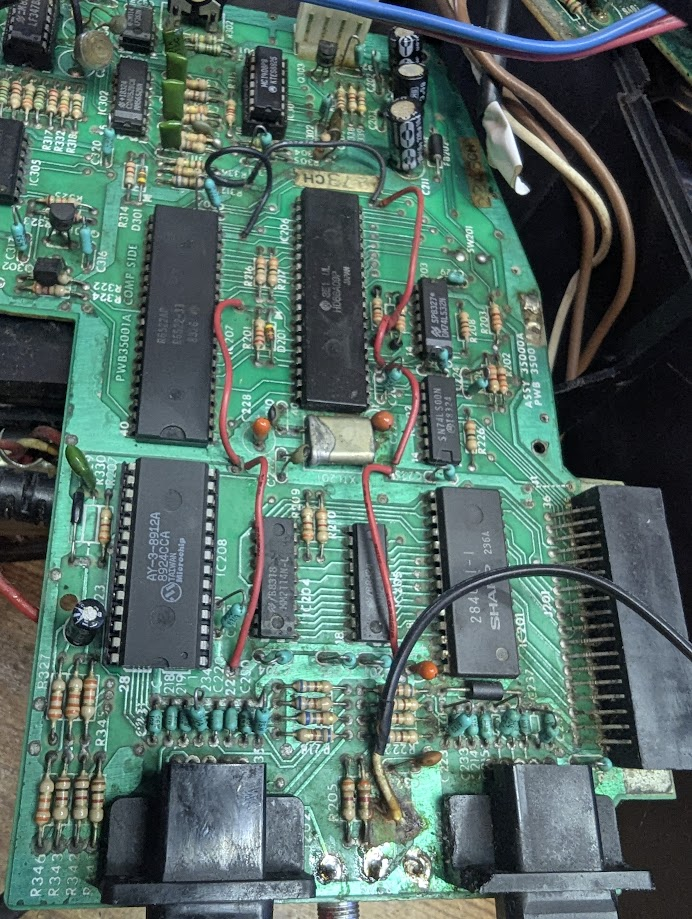
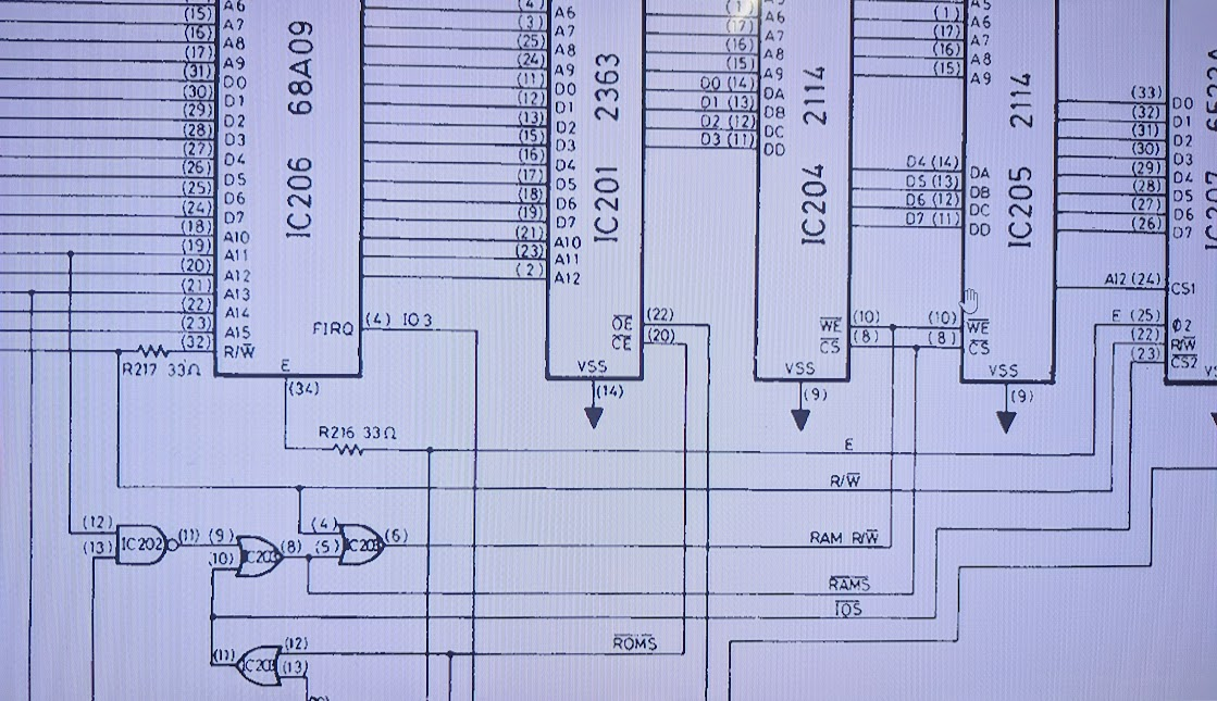
IC202 SN74LS00 is a logic chip for rom enable and indirectly ram enable measures a slightly suspicious 4.7v. This can be indicative of a faulty chip although it doesn’t get hot. This is a logic chip of nand gates so I’m going to check the gate pins on the oscilloscope and look for any incorrect logic or poor signals. There was a similar symptom on the sound chip earlier.
The wiring is very brittle but it is over 40 years old although the unit was very dirty when first opened with the boards covered in gunk. The audio wire had come loose. Reconnecting it I was hoping this was the reason for no audio but no such luck.
I was going to pull logic chip IC202 but its voltage now measures 5v consistently.
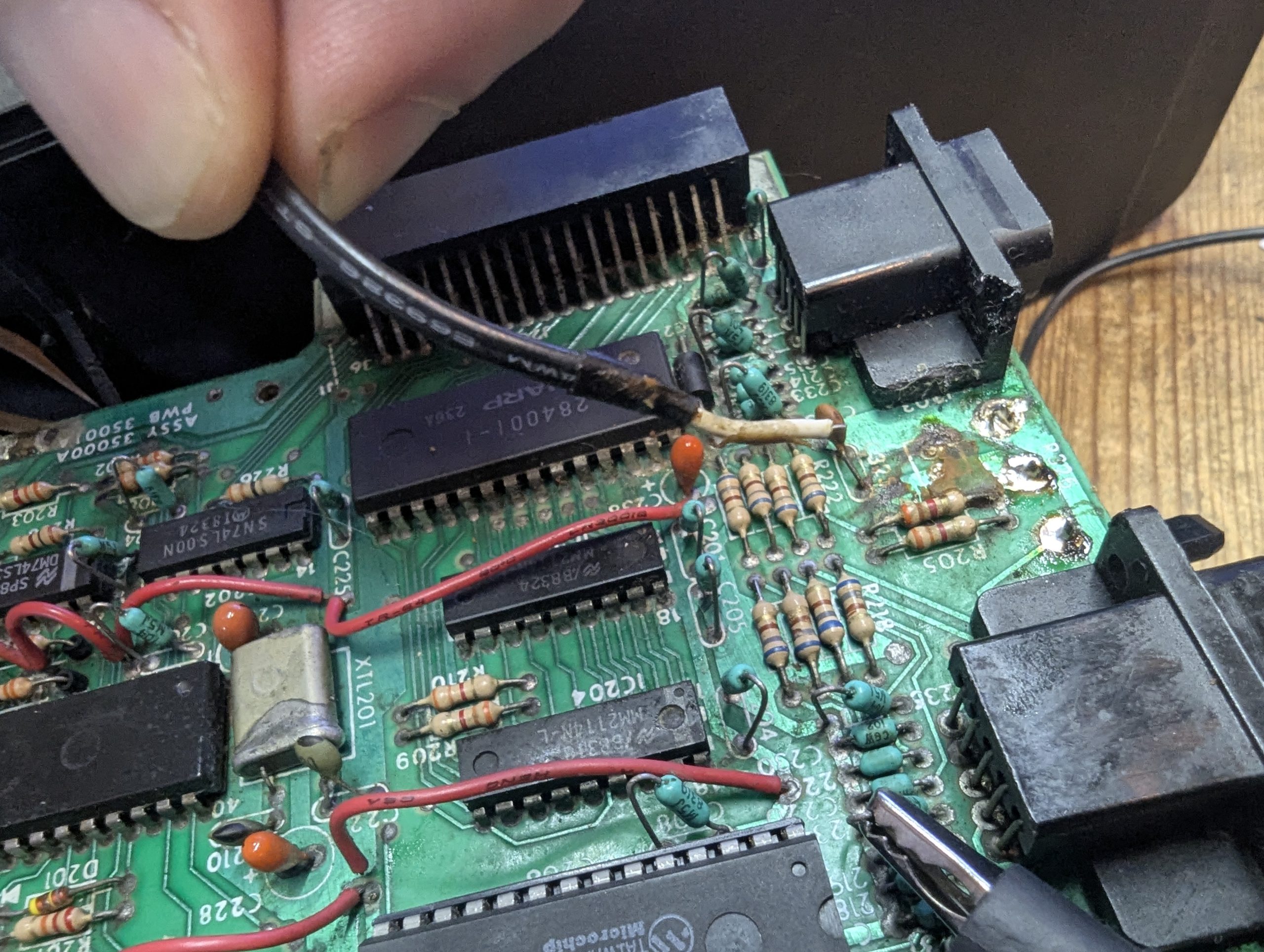
IC203 Read Write Ram
I have connected to pin 32 of the CPU and get activity on boot which gives regular pulses sometimes, or stops and flat lines after a few sceonds or emits a very weak signal. Suspect.
Tracing this signal line leads to ram write enable via the IC203 74LS32 nand gate. The ram/read signal has no activity which is strange so I’m going to pull IC203 and socket /replace if necessary.
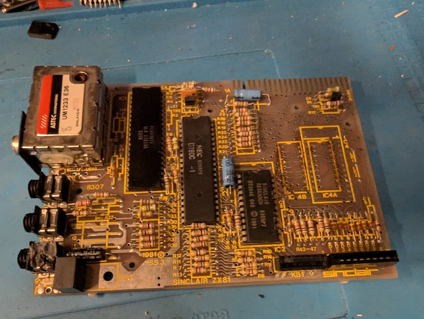
I discovered the old Sinclair ZX81 has the same ram so decided to harvest until replacements arrive.
Pulled, socketed and replaced ram in the Vectrex
Sadly no activity at the Ram WE pin 10. I suppose its possible there is no ram access on boot, Regardless there is still no sound or display from the Vectrex.
The Usual Suspects
So it looks like the CPU , the 6522 or the Rom are faulty and thats just the logic board. I suspect more issues on the power board but the voltages are being supplied correctly. The CPU has got an intermittant fault with the pin 32 signal but after a couple of resets it settles down so I’m hoping it is working when the signals are stable but will need to be replaced or at least socketed.
This Very Dead Vectrex Repair is now more undead but the repairs continue. I’m going to look for more clues and report back soon.
Alot has happened
Its been a couple of weeks as work intervened and progress on the Vectrex was slow and frustrating.
So I socketed the CPU, 6522 PIA and the 2364 ROM.
Purchased 68B09P cpu’s to replace the 68A09 as they were compatible and cheap from our chinese friends.
I already had 6522’s having done a number of C64 and Vic20 repairs and swapping in a new one improved the activity of the address and data lines but it still didn’t boot.
I decided to confirm the new 6522 was working ok by putting it in a Vic 20. There are two 6522’s in a Vic 20 one for the keyboard and one for disk drives. I installed the 6522 in the Vic20 and tested loading a game from disk. It failed. The new 6522 was bad!!. I tested another 6522 and it was ok.
Installed the new new 6522 turned on the Vectrex and….still no joy. Damn!!
The Rom
There were still issues on ram read/write enable and rom enable lines as pin 22(Rom Enable) of the IC201 was constantly high and should be oscillating.
I therefore socketed the ROM and tried to read it in the eprom programmer. The right side pins of the rom all showed as failed on the programmer software. This was definately a failed rom.
I therefore needed a replacement rom. The original is a 2363 chip which is a read only non programmable mask rom. However there is a pin compatible programmable rom 2764 which can be used and I had a few of these. Further checking revealed that I could use a 28C64 which was much better than the 2764 as it could be electrically reprogrammed and didn’t need UV light to erase it. The next problem was I didn’t have a Vectrex rom file to program onto the new rom. I spent the next few days finding the rom files which wasn’t easy.
Turns out there are three rom versions depending on the part of the world and time the Vecrex was released.
7931 – First release for the North American GCE machine
B796 – Second release for the Milton Bradley Machine found in Europe
7ADB – This is the final Milton Bradley rom version with the a fixed version of Mine storm allowing levels past 13 and therefore the one I chose.
I made a new rom, installed it and..still didn’t boot. Damn!
I was going round in circles for a while checking address and data line activity. I decided the check the power board for issues.
Decided to check transistor BU407 for any shorts. It was fine.

Wild Goose Chase
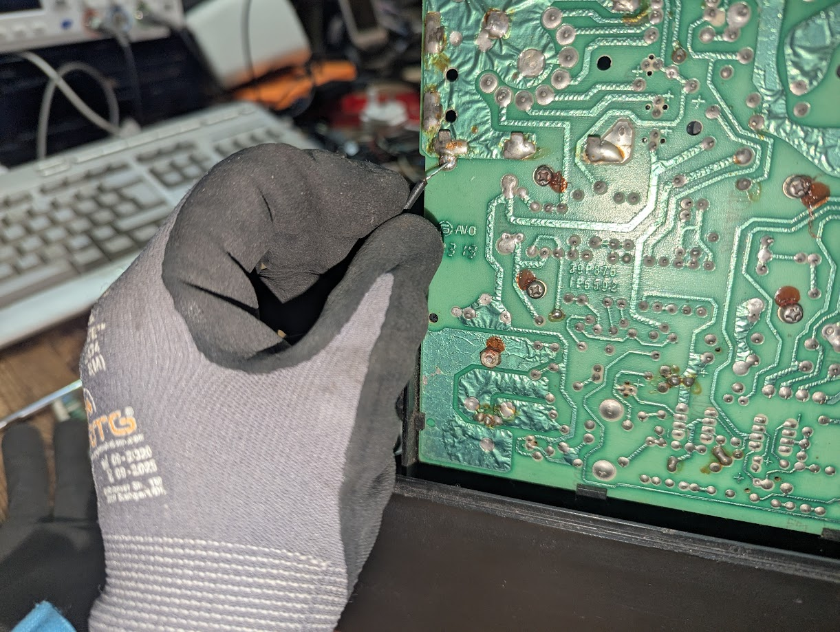
The hardest working chip in the Vectrex is IC401(LM379S). It deals with the scan coils for the display, is located under a massive heat sink on the power board and is a common point of failure. There are also capacitors under this heat sink which may need attention so I decided to investigate.
The heat sink is the big black chunk of metal on the left board under the neck of the tube. Sadly I didn’t get too many pictures after removing.

Pins 3,4,11,12 of IC 401 should have continuity to the negative of capacitor C411. This capacitor was missing on my board and it looked intentionally so. Still the pins correctly showed continuity. Pins 5 and 10 did show they were grounded and this was suspicious as the schematic doesn’t show they are grounded.
The two capacitors under the heat sink were also fine but I decided to move them to the underside of the board incase they needed replacing in the future and so this could be done without needing to remove the heat sink.
There can also be issues with the heat sink grounding the rectifiers so I replaced the thermal paste on these and IC401 and ensured the thermal membranes were seated correctly so not to allow any shorts to ground.

If this Vectrex ever did work then the at least the power board heatsink was serviced.
First Sign of Madness
Repeating the same thing and expecting different results. I was going round in circles trying the same short circuit and bad capacitor tests on the power board and was beginning to think the Vectrex Very Dead Repair was going to be all for nothing.Finally I came to the conclusion that because 5v, -5v and the -13v were being supplied correctly to the logic board that I should be able to get the logic board to boot and get the Minestorm game sound. I therefore returned my focus on the logic board.

All the socketed chips had been confirmed good except for the CPU so decided to crack open a Dragon 32 and try the cpu in it. The Vectrex CPU runs at 1.5Mhz and the Dragon 32 6809 runs at 0.89Mhz I thought there might be issues but if it boots even for a short period then that is a good sign. It didn’t.
It did however show a set of black and white jail bars and all the other 5 vectrex Cpu’s consistently showed the same so there was a good chance that they were good, unless they were all bad. Fingers crossed.
I decided to swap out the remaing unsocketed logic chip IC202(74LS00).
and…..
It booted!!!!, It made the Dah Dah! sound. I could here the game demo starting and playing through the speaker. Finally after 3 years on a shelf and a few weeks of toil the Vectrex very dead repair was paying off.
Fixed?
So socketing IC202 and reseating the ROM were the last things I did that brought it to life. There must have been an intermittent connection on the rom and or IC202. I resoldered the rom socket just to make sure.
Now to connected the screen up.

YES!!!!. The screen works. There is a bright dot in the center but that was because the brightness was set too high. A slight adjustment and.
Finally a working Vectrex.
Whats Next. Lets make a Joystick
The Vectrex service manual has this circuit diagram

So a few components later and I made this

I must admit I’ve had these parts sitting on a shelf for three years waiting for a working Vectrex to come along.
The Final Test
So just need to make a enclosure for the parts and then I’ll report back.
I’ve also had the parts for a Vextreme cartridge sitting around for three years somewhere but that build will be on a separate post.
I forgot…. Elite, yes thats why I was doing this. It turns out that this game is available through something called Pitrex. This is currently in development and is a Vectrex cartridge which will allow a raspberry pi zero to run Vectrex games and enhanced games to display on the Vectrex vector screen. Sounds interesting but again it will be another post.
Vextreme
Built and works fantastic. Didn’t know about all the developer stuff you can do with this cart. Then again not looked into it for 3 years so probably forgot.
I was very apprehensive about the micro soldering required for these tiny pins but my skills have improved a little over the years and the heat gun sorted this no problem. I’ll make a separate post on this device.


I’m also on Facebook and Twitter X and BlueSky