This Aussie Commodore 64 Repair began while I was driving my Delorean when I accidentally hit 88mph and ended up in the 1980’s. Whilst there I picked up a couple of classics.
Then I woke up.
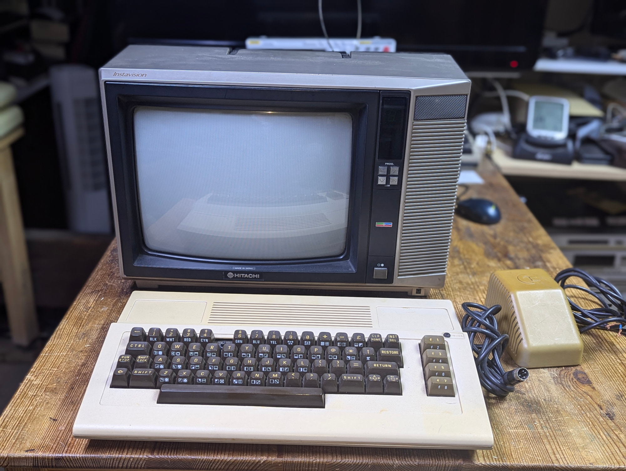
Strange thing is I found these left on my workbench. A Hitachi CPT1473 and a Commodore 64 Australian edition. Which was nice.
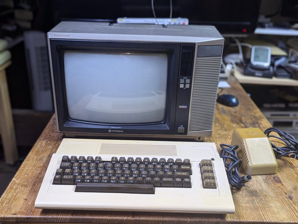
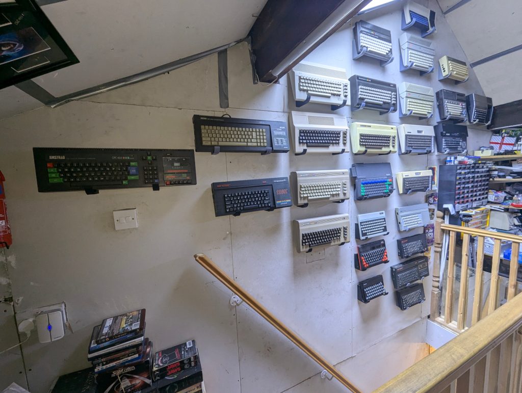
Not got a Aussie C64 so I’ll put it on display with the other 64’s, once its working, as only working Retro’s are allowed on the display wall.
Initial Checks
First things first. Check the PSU. There’s a tool for that, available here. A Nice green glow says this PSU is safe to use. It turns red if the PSU has failed. Look at the browning on that PSU.
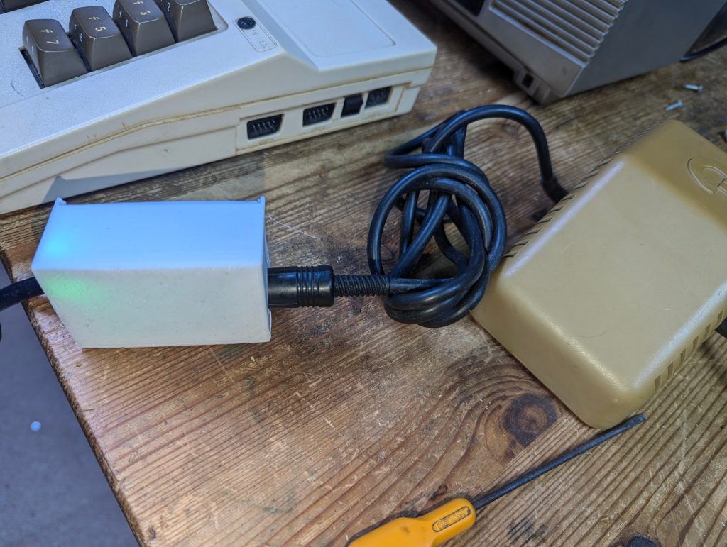
There is a number 5 key missing but I’ll deal with that later.
Lets open up the C64 and have a look.
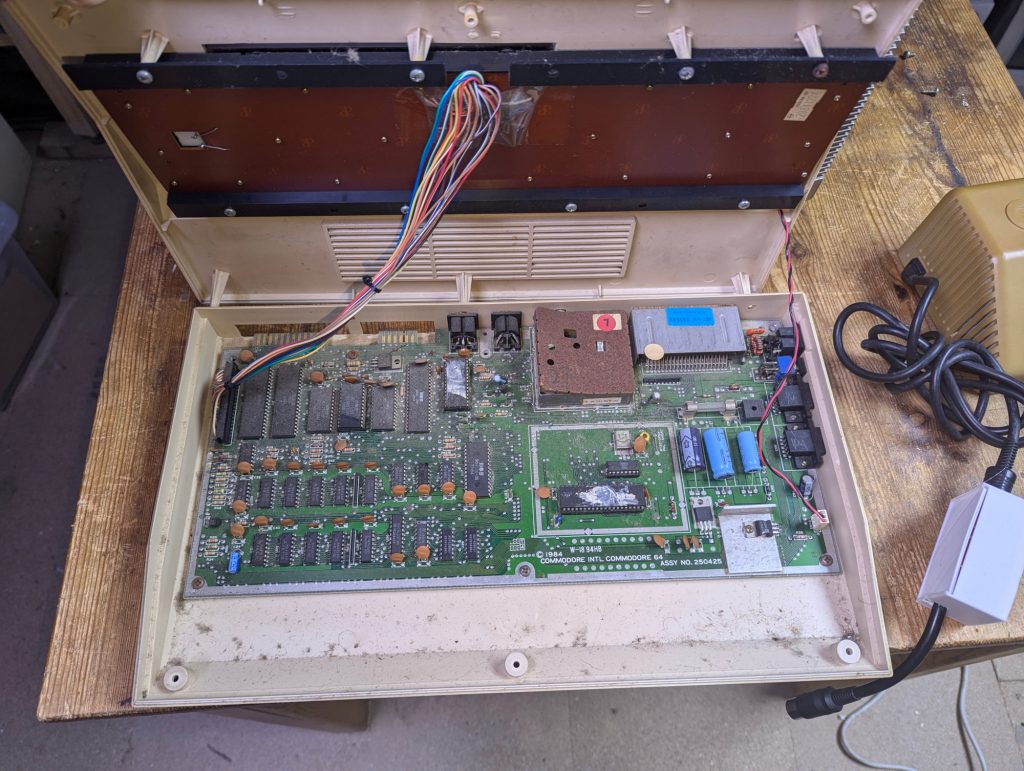
A bit dusty but I’ve seen worse. That RF shield looks a bit rusty though.
Lets remove the motherboard.
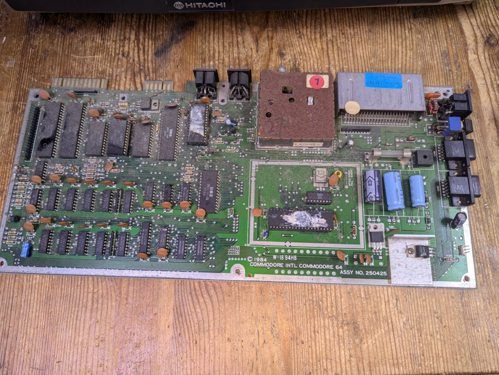
I actually dusted this off but there dust appears to have returned ??.
Ok time to give it a more serious clean. After cleaning and checking both sides of the motherboard there were no obvious signs of failure.
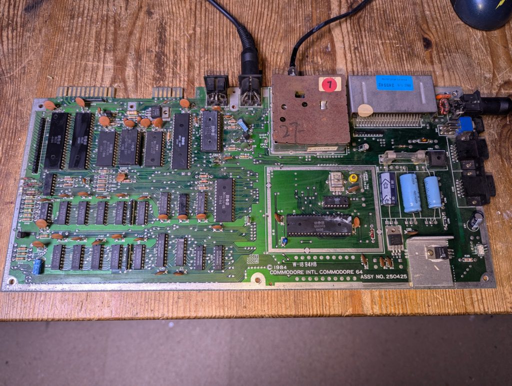
Thats better. I can actually see the markings on the cips now.
Next its time to check the socketed chips in a working UK C64.
First to test the kernel in a known working machine.
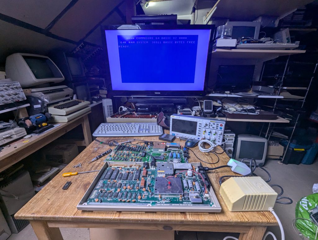
Good news the Kernel is ok now the Vic2
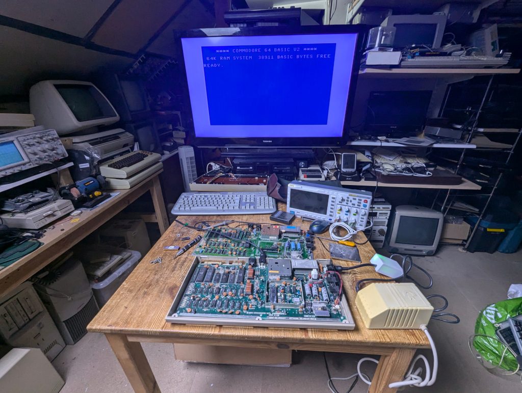
Great news the Vic 2 is good so now the SID.
Popped the SID into a working C64 and the SID works which was a surprise. Original working SID’s are getting rare now and are worth as much as the computer.
The fuse checks out ok so It’s time to bite the bullet and give it a power up.
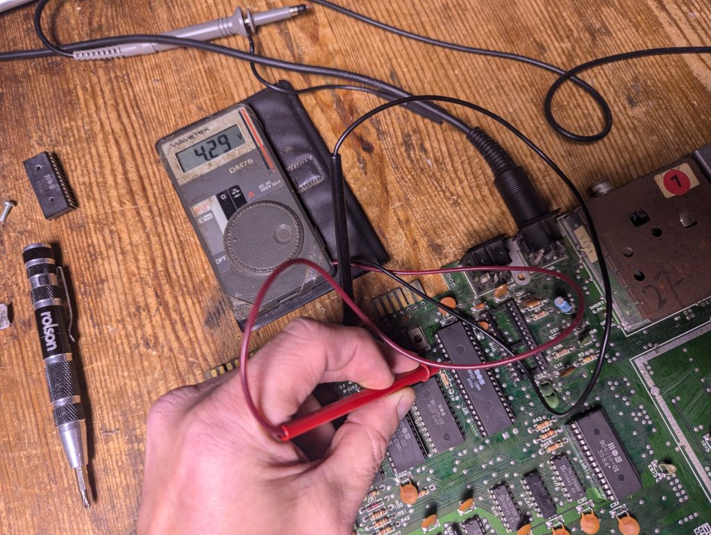
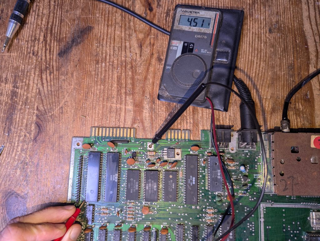
Checking the voltages
Top Left 12v regulator looks ok
Top right 5v regulator looks ok
Bottom left Ram voltage is a little low
Bottom right CPU voltage is a little low and the lowest of all
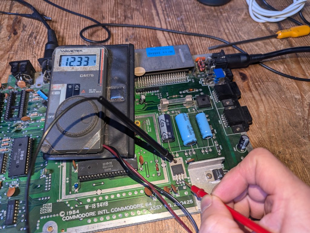
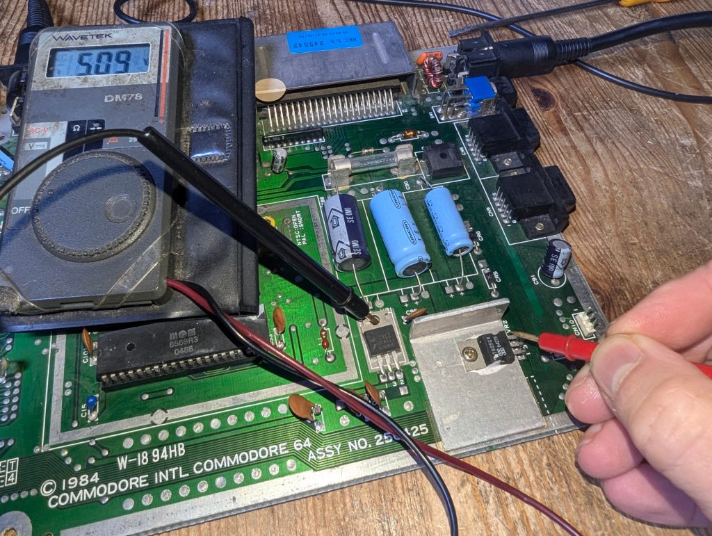
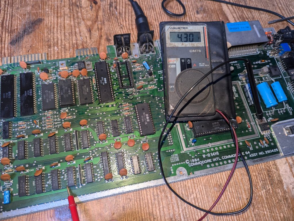
Below the CIA voltage if a bit low at 4.51v
The 5v rail appears a little low coming lowest at the CPU with 4.29v. The 12v checks out ok at the Vic2
I remembered the SID 6581 is not necessary for boot up so I removed this to preserve it until the machine is working normally.
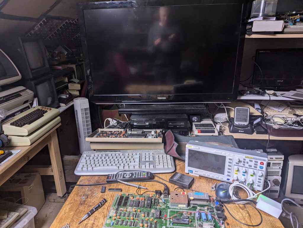
Sadly it just gives a black screen but at least its some sign of life.
After a few minutes of power on there are no chips getting hot so lets try the dead test cart.
Dead Test Cart
This is bound to reveal the fault…
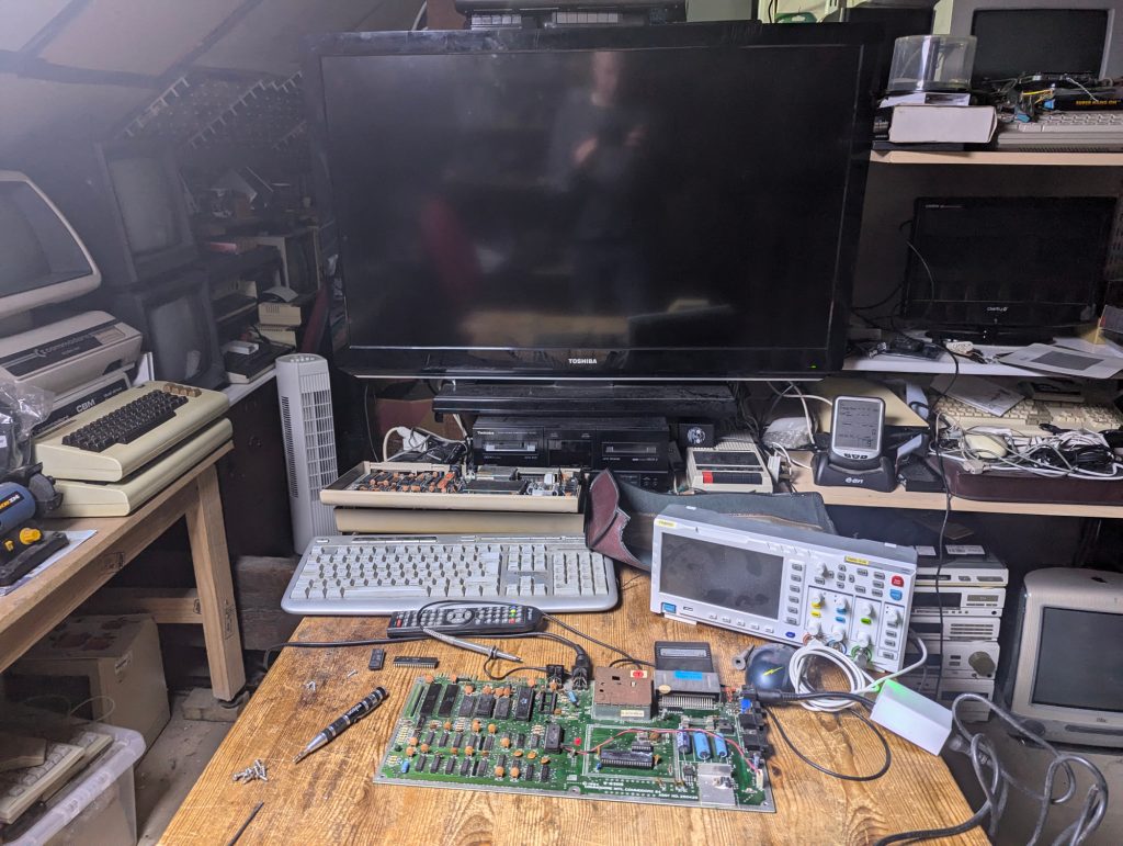
Nope!. Still a black screen which is a real mystery.
For the dead test cart to give a black screen generally means a bad CPU, Vic2 or PLA. I have checked the Vic2 in a good machine already so we can rule that out. Lets get the scope on and see what we can see.
Signals
Here is the 6510 CPU pinout.
First to check for a clock signal on CPU pin 1
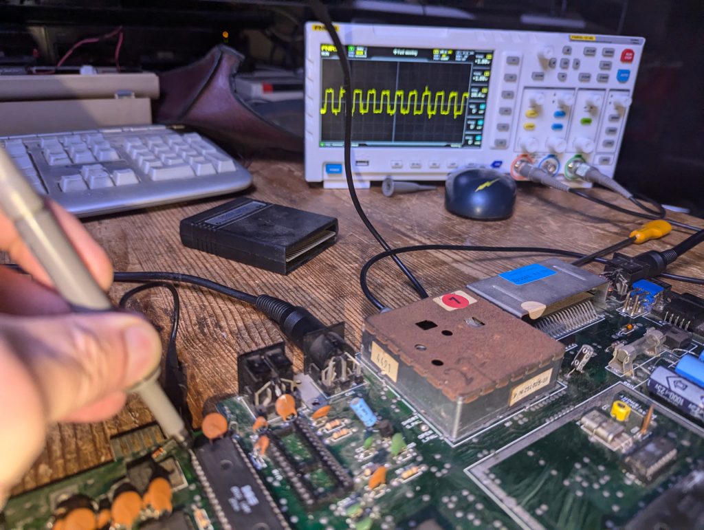
Appears ok.
The RES (Reset) pin 40 should start high and go low immediately.
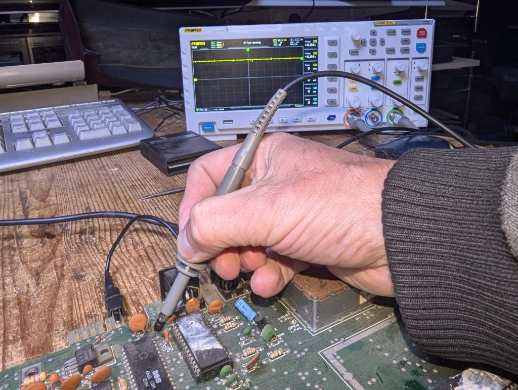
The Reset signal stays high.
The IRQ pin 3 should start high and go low
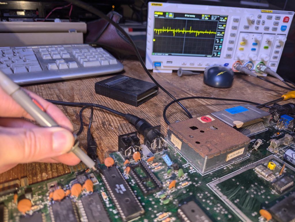
IRQ pin stays high and is a bit noisy.
As the PLA is such a common point of failure I decided to socket it.
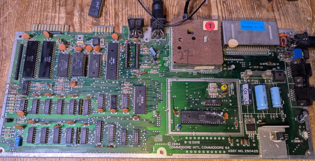
The PLA worked fine in a good C64 so on to the next potential.
I decided to investigate the IRQ line on the CPU.
The IRQ line on the schematic reveals it is linked to CPU, Vic2 and CIA1 chips. We know the Vic2 to be working so if I disconnect the IRQ pin on the CIA the dead test cart should come to life if the CIA is faulty and the cause of the stuck IRQ line.
I didn’t need to desolder the whole CIA so just desoldered the IRQ pin 20 and made sure it wasn’t making a connection.
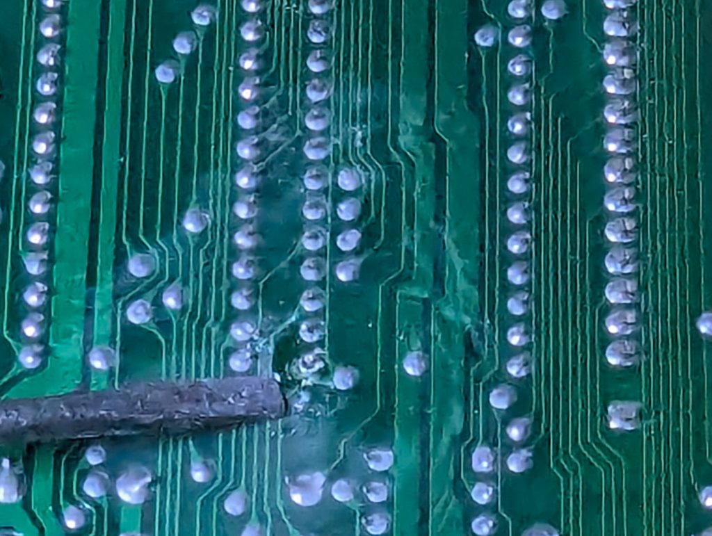
It is disconnected, honest.
Sadly the IRQ signal remained high at the CPU end while the CIA1 IRQ signal remained low. Also the dead test cartridge remained unresponsive with a black screen so I’m going to socket the CPU and try it in a working C64.
Desoldered the CPU.
Now to test it in a working machine
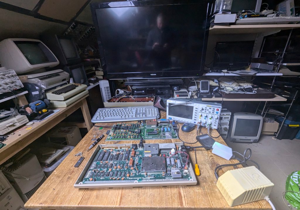
Its a black screen so the CPU is dead as a dead thing.
PSU Retrobrite
During this Aussie Commodore 64 Repair you may have noticed in the later photos above that the PSU had changed. Thats because I decided to stick the original PSU in the retrobriting box. Took a couple of days using the peroxide cream method.
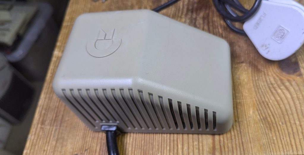
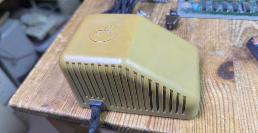
Not a bad result.
CPU Replaced
So lets put a good CPU in and see what we get.
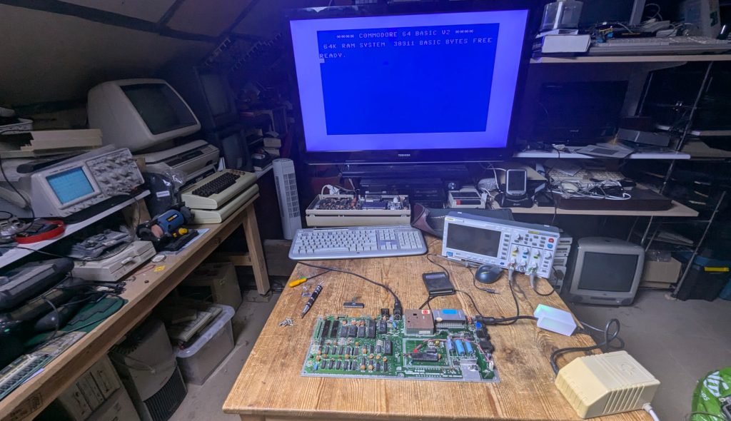
Good news RAM size correct screen stable.
So lets test with the dead test cartridge once more.
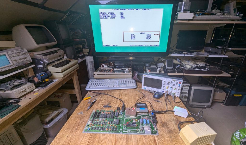
Damn it!. Failure on U21 which is the first, bottom left Ram chip.
But wait, the Ram Free is 38911 bytes on the boot up image above so whats going on??
I just decided to socket U21 and replace with a new 4464 Ram chip.
Ram Replacement
I’d just like to say this was a nightmare. I used exactly the same procedure to remove the CPU and PLA which were relatively easy. For some unknown reason this ram chip did not want to come out. I ended up heating the legs from both the top and bottom using a soldering iron on top and the desoldering gun on the bottom and finally the solder started to come out. With the ram finally removed there was a bit of damage to a track and a pad partially removed. The repair was pretty easy with some tiny gauge wire on the track and the pad had enough left to just solder in the socket. What a PAIN!
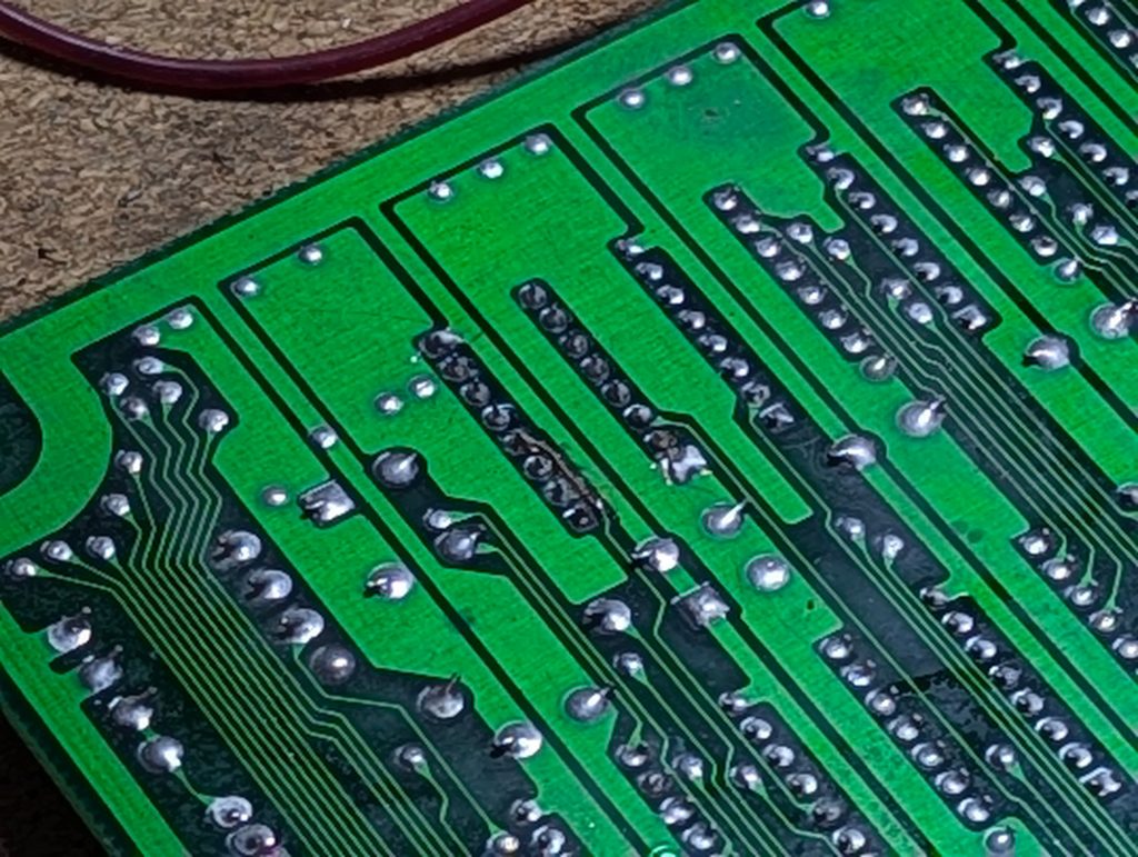
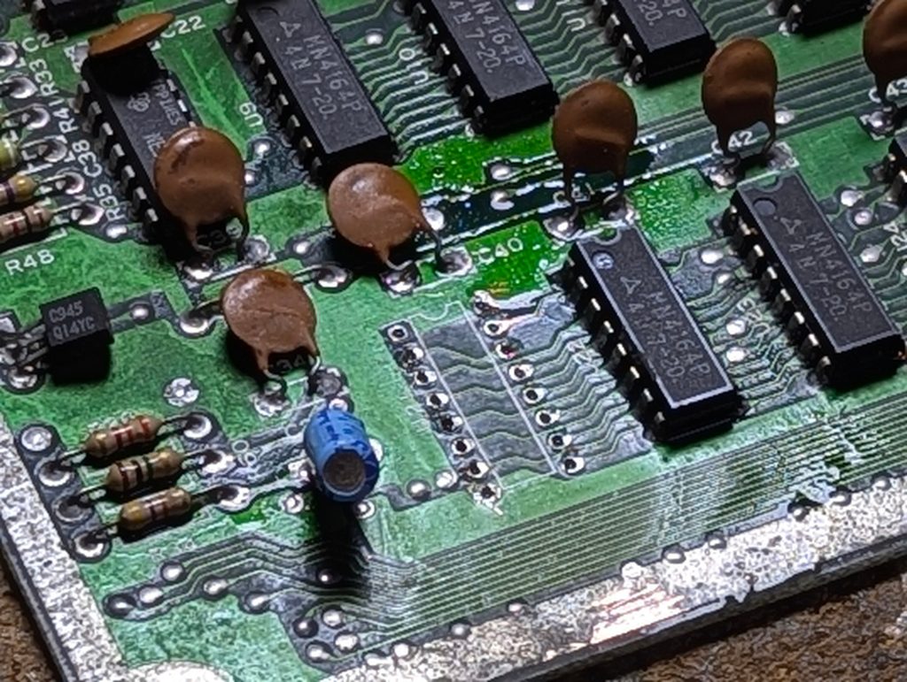
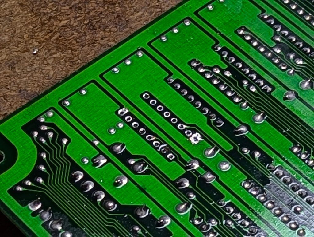
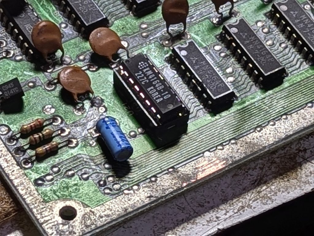
Finally a new socket and Ram chip installed. Hope I don’t have to do that any more!
Dead test time, Again!
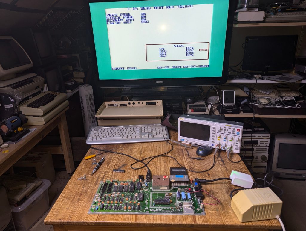
Damn it!!!!!!!!
U22 Ram chip has failed. Time for a break to consider whats going on as I’m not sure these Ram chips have actually failed.
I’ll come back to this once I’ve calmed down 😉
This Aussie Commodore 64 Repair will not defeat me!
Twilight Zone
I feel like I’m traveling through another dimension, a dimension not only of sight and sound but of mind. A journey into a wondrous land whose boundaries are that of imagination.
I purchased a new CPU which arrived today so I plugged it in and gave things a test and it appears that, well, just look at the photo.
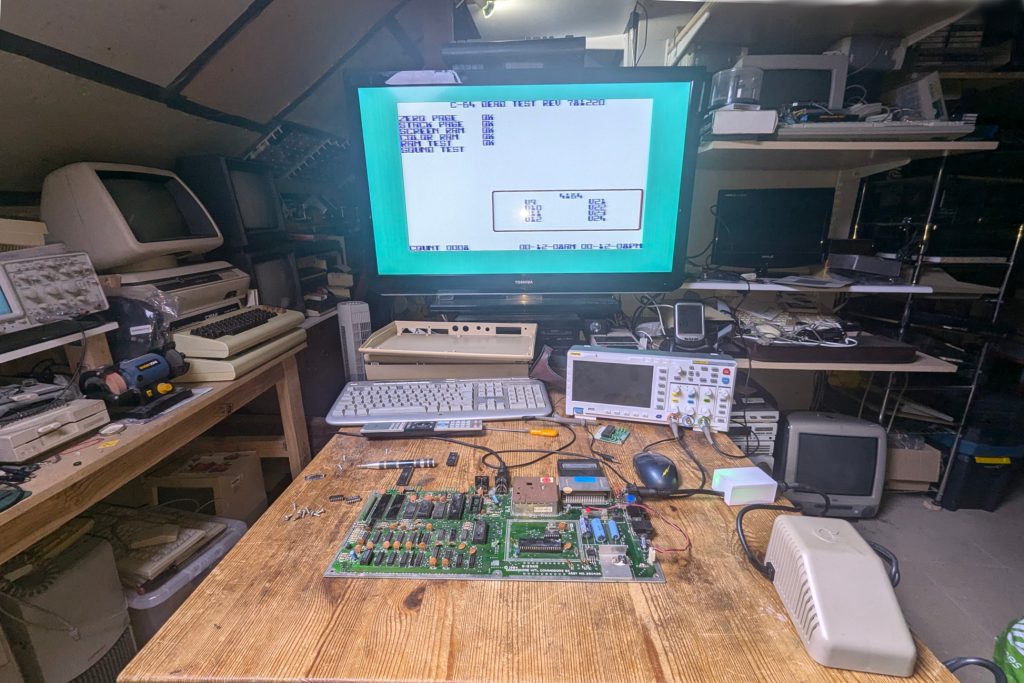
Everything checks out ok. I even let it loop through the tests another 8 times and power cycled numerous times and its all fine. How queer!
Fixed?
Well not quite fixed but we are getting close. The next job was to tackle the keyboard and the cosmetics.
Not sure what conditions this C64 had to endure but getting these keys off was a complete nightmare and look at the state of the springs.
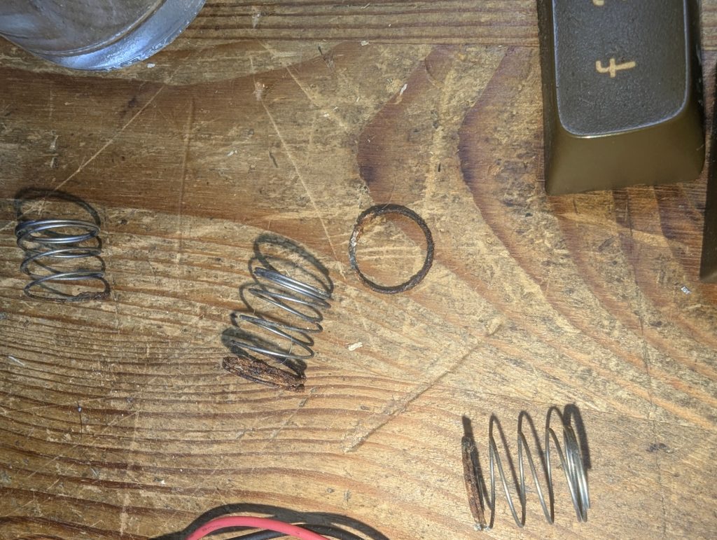
The keys were so difficult to remove even my poor custom made key extractor died. It was like they were superglued on. I’m beginning to understand what happened to the original ‘5’ key. Someone probably used so much force that the stalk snapped.
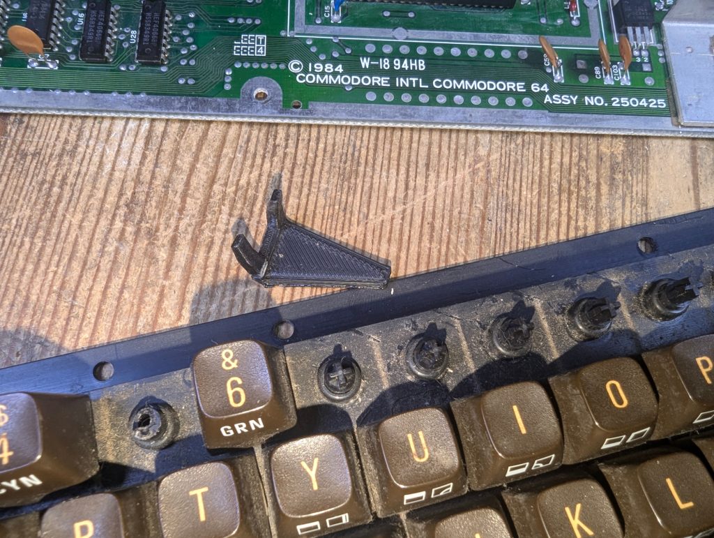
I purchased a ‘5’ key which doesn’t quite match the others even after a clean.
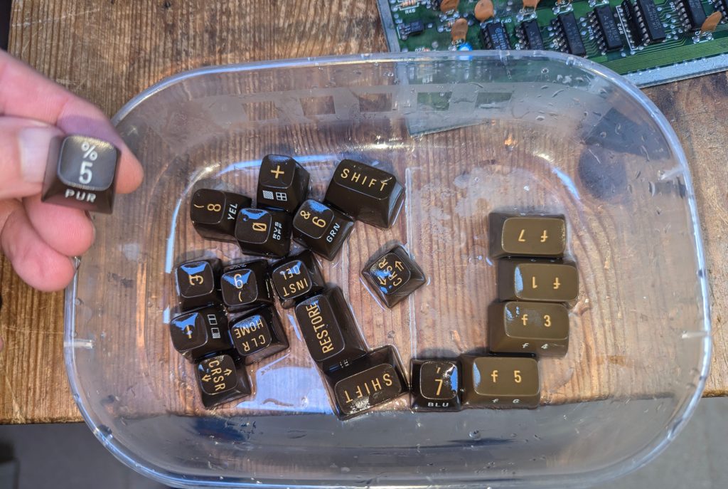
I decided to try a new retrobrite method which didn’t involve the messy peroxide cream and UV. I thought I would try 12% heated peroxide sous vide method.
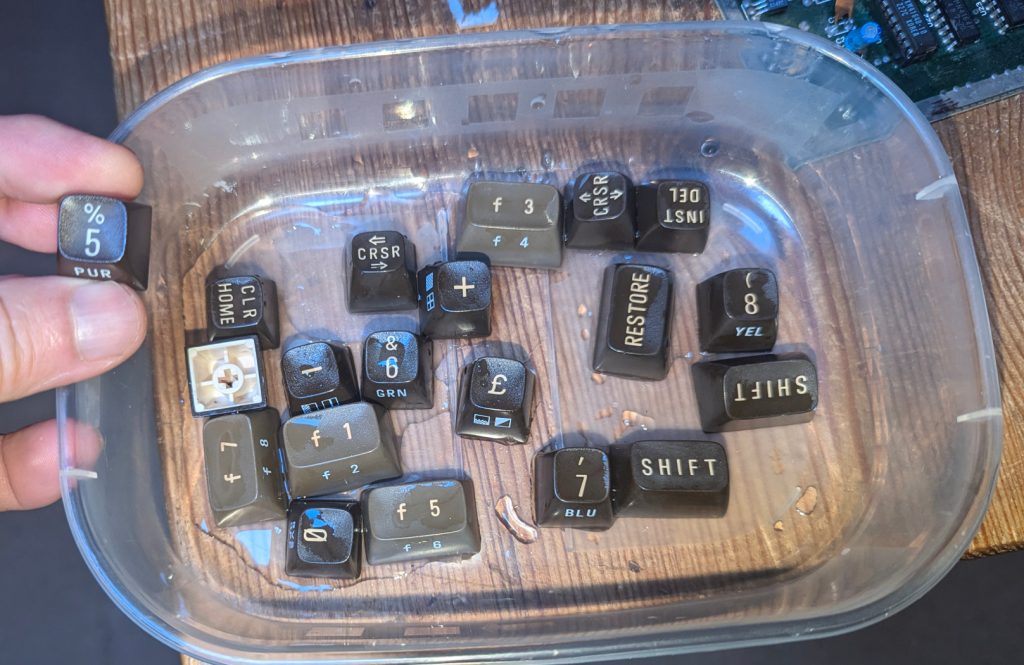
This method took 2 hours and gave encouraging results but I think another hour is required as there is still a little bit of browning compared to the new 5 key. The function keys have returned to a more normal grey colour but the letering still has a slight brown tinge. The peroxide cream method invariably takes 5-12 hours to get similar results.
I could probably get retrobriting down to 1 hour with UV light applied but need to protect the electrics from the peroxide splashes and fumes somehow and also fix the orientation of the keys to stay flat pointing towards the UV while being submerged. Food for thought.
Retrobright Dangers and Fixes
Apologies its been a while since I updated this. The reason is everyday stuff got in the way and I was upset with the retrobright result.
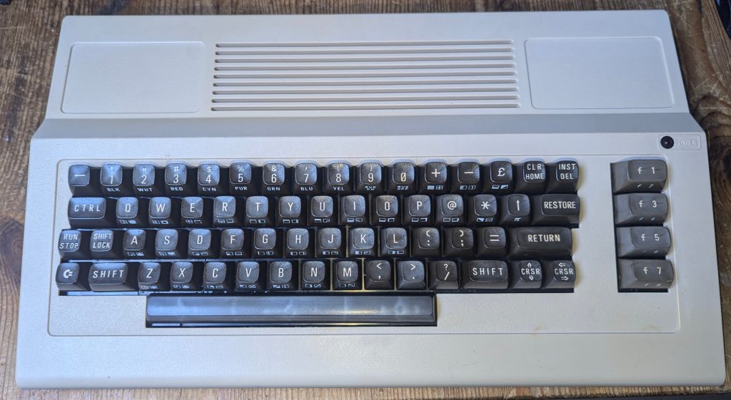
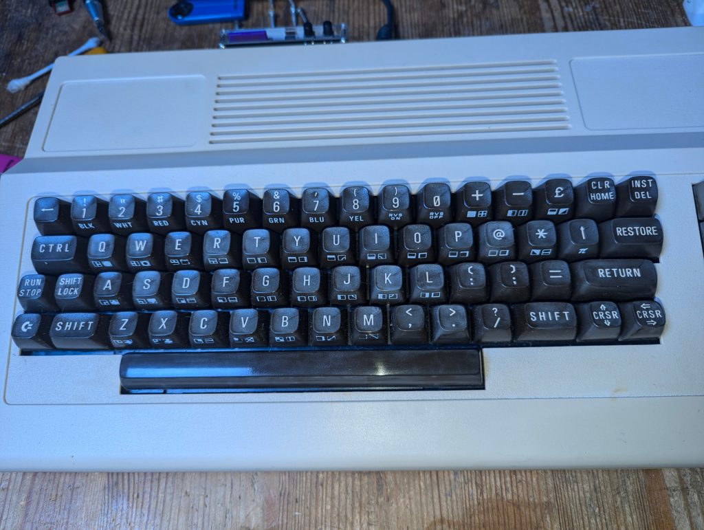
The spacebar was ruined and the keys went quite chalky and this was not apparent while the keys are wet. Ahhhhhhgh!
But wait, not all was lost. After some research and experimenting with various cleaning products there was a small glimmer of hope.
This picture emphasises how bad the chalkyness on the keys got and the streaking on the spacebar. But notice the right side of ther spacebar. This is after some experimental polishing with some household cleaning creme’s. The streaks have all but gone!
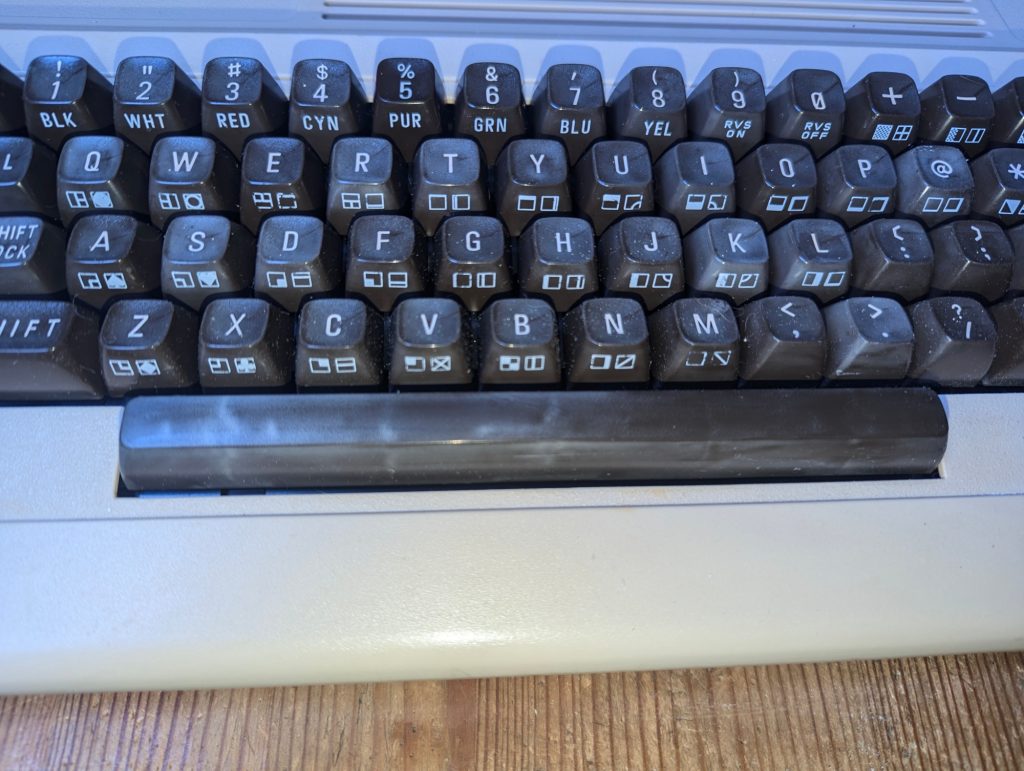
The spacebar is finished, well just about. It needs a bit more polishing. As this post is getting a bit long I’ll detail the retrobrighting recovery technique in another post as I think it deserves its own section.
And Finally
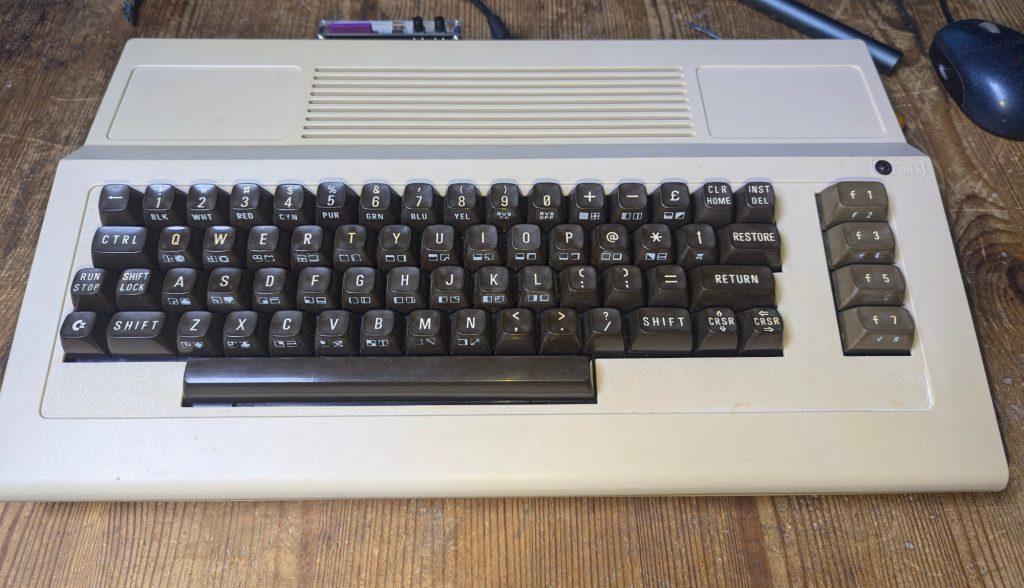
Finally back in one piece. The keys have all been restored and the machine is returned to its former glory. Massive retrobriting lessons have been learned and the result a successful restoration of a classic piece of history.
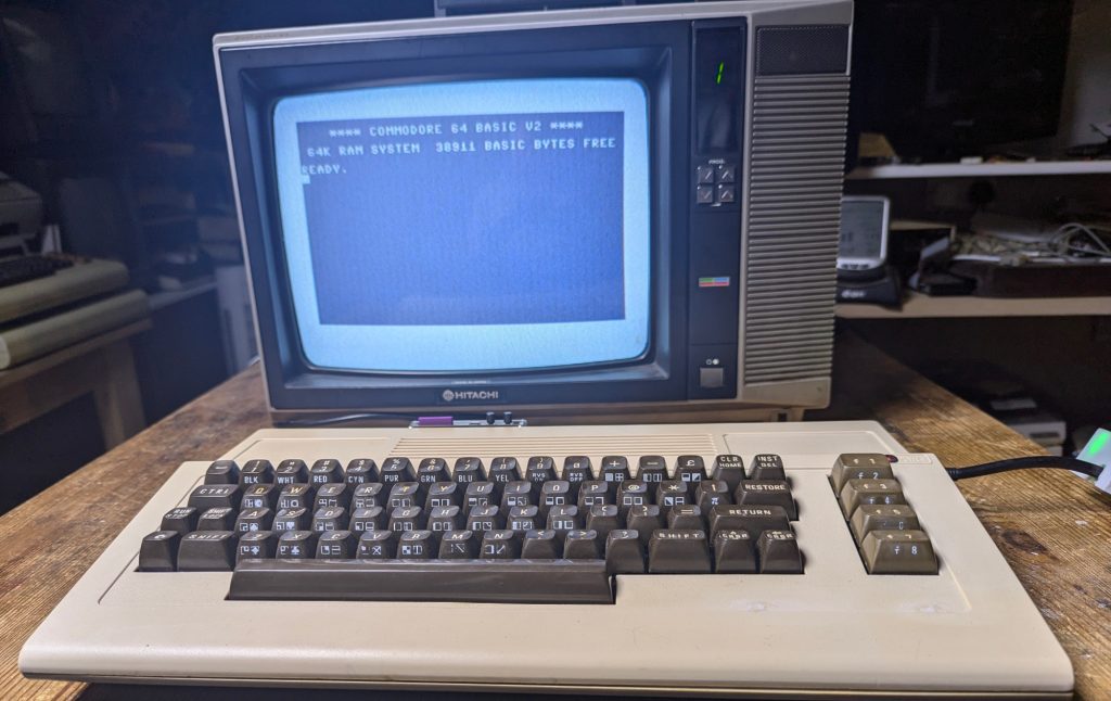
Just to show it does work.
Thought I would show of the Hitachi output. This is actually an RF signal.
Decided to put it pride of place on the Retro wall of fame next to its Commodore friends.
